Antenna work: new 6/4m beam and setting up a 20m windom antenna

After a trip to OJ0 in 2023, I decided to buy one of the 6/4m yagi antennas used by 1UW during the expedition. My plan was to mount it up by the cabin, using the already existing pole currently being occupied by my 20m vertical antenna. This new antenna in question is the EAntenna 5070-OWA8, a 8-element yagi antenna with the elements evenly divided across the 6 and 4m band. The two bands share the same feedpoint, meaning a duplexer is required if one is to use different transceivers for the two bands.
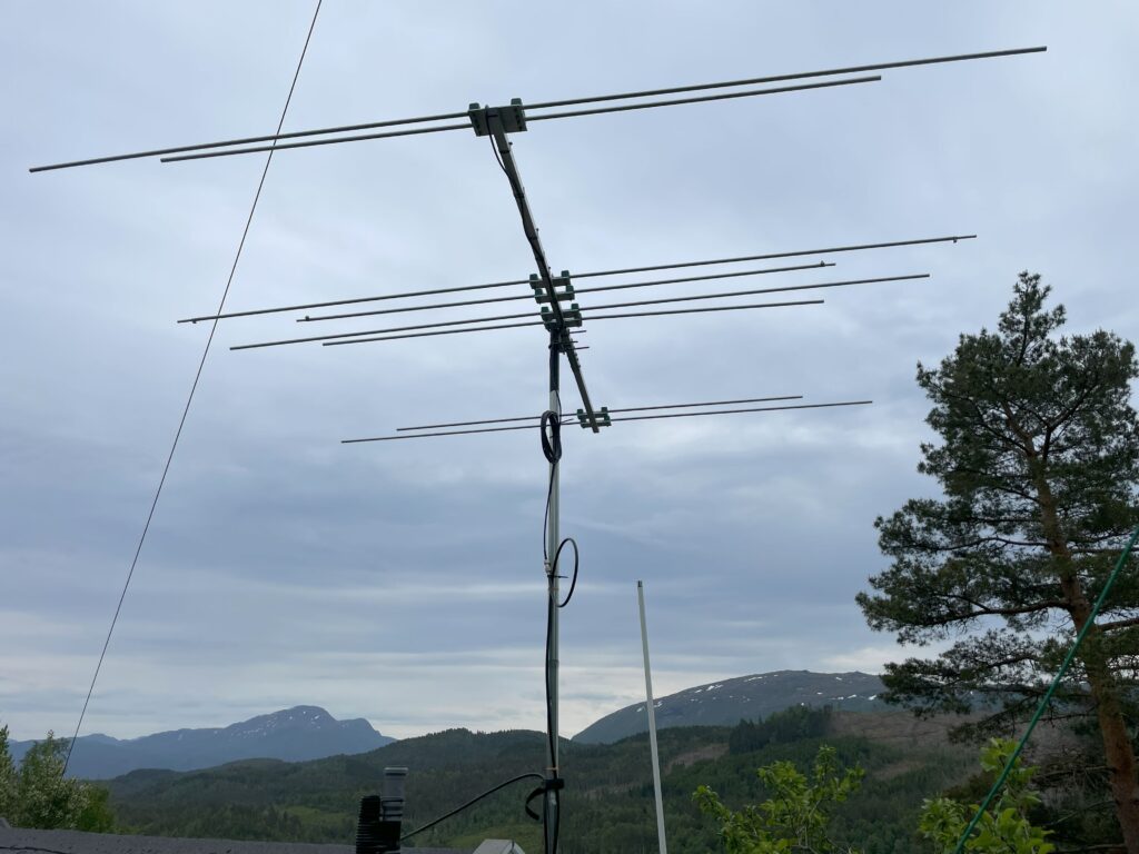
The new addition to the radio shack.

The antenna is fairly easy to install, only having to screw the elements into the center pole once the correct order has been clarified. This first install was just a proof-of-concept, confirming whether or not 6 and 4m was of any interest at this QTH. The first results were quite disappoiting, not having any luck reaching other operators using FT8. Not having the NanoVNA with me neither, I could not find what frequency it was currently tuned for. For now, the antenna was at least mounted up and hopefully only minor adjustments were required to make it operable.

During my recent visit, I found that I had put the feed cable across the center pole, and not straight down like pictured in other installs online. As this is fairly plug-and-play antenna, I immediately thought for that to cause some disruption to the antenna.
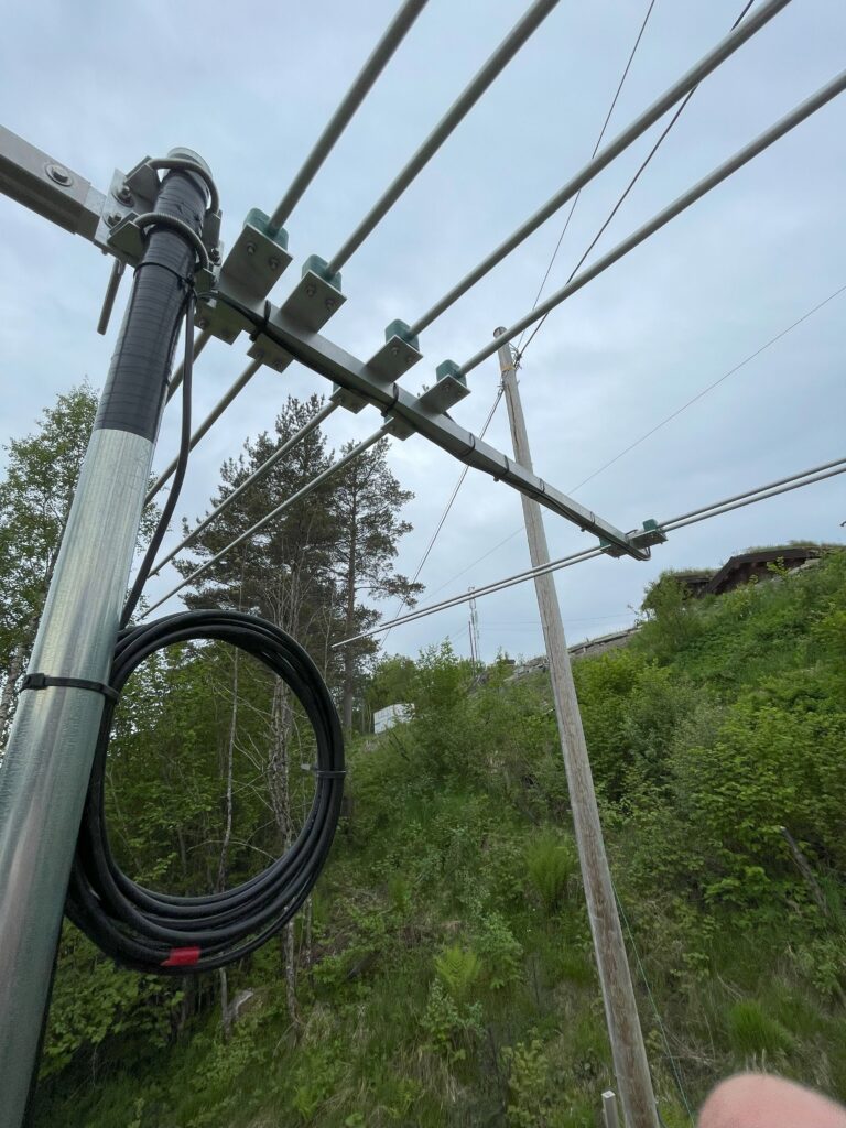
The first attempt at installing the EAntenna-yagi, with the wire going over and under the center rod, and the cable coiled up quite a lot of turns!

Another quite obvious culprit was the tuning of the driven elements for 6 and 4m, which has a innter tube allowing for a limted adjustments. As this antenna was used quite close to a metallic roof last time, the move to its new QTH could definitely call for some adjustments. After moving the cabling and tinkering with the adjustable elements, the antenna showed a much more promising SWR measurement, with the center frequency at approx 50.300Mhz.
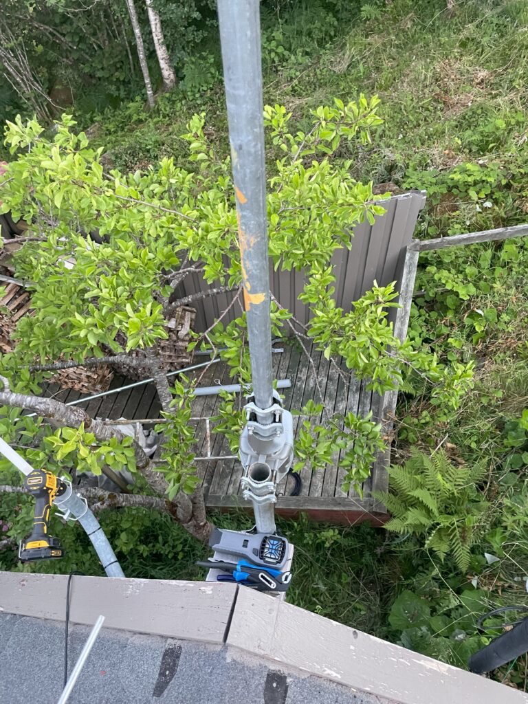
Doing mast work alone, the available mast attachment is handy as a parking spot for your equipement. Notice the mosquito repeller right below the rotor.

Next came the time to install the antenna rotor, which I had also previously used at OJ0 with good results. The antenna rotor is quite simple, consiting of a 3-wire controller and the outdoor rotor-unit itself. The rotor is Conrad 284971, though with the same controller also known under the name HyGain AR-303X. As the old mast consisted of two 1.5m mast rods that had been irreversibly put together (by design, of course), I had to find some other rods. Luckily I had a heavy-duty steel rod that I once received from a friend, plus another one of the light-weight 1.5m aluminum rods readily available. The former was placed on the bottom, with the lighter one placed on top of the rotor for the antenna mount.
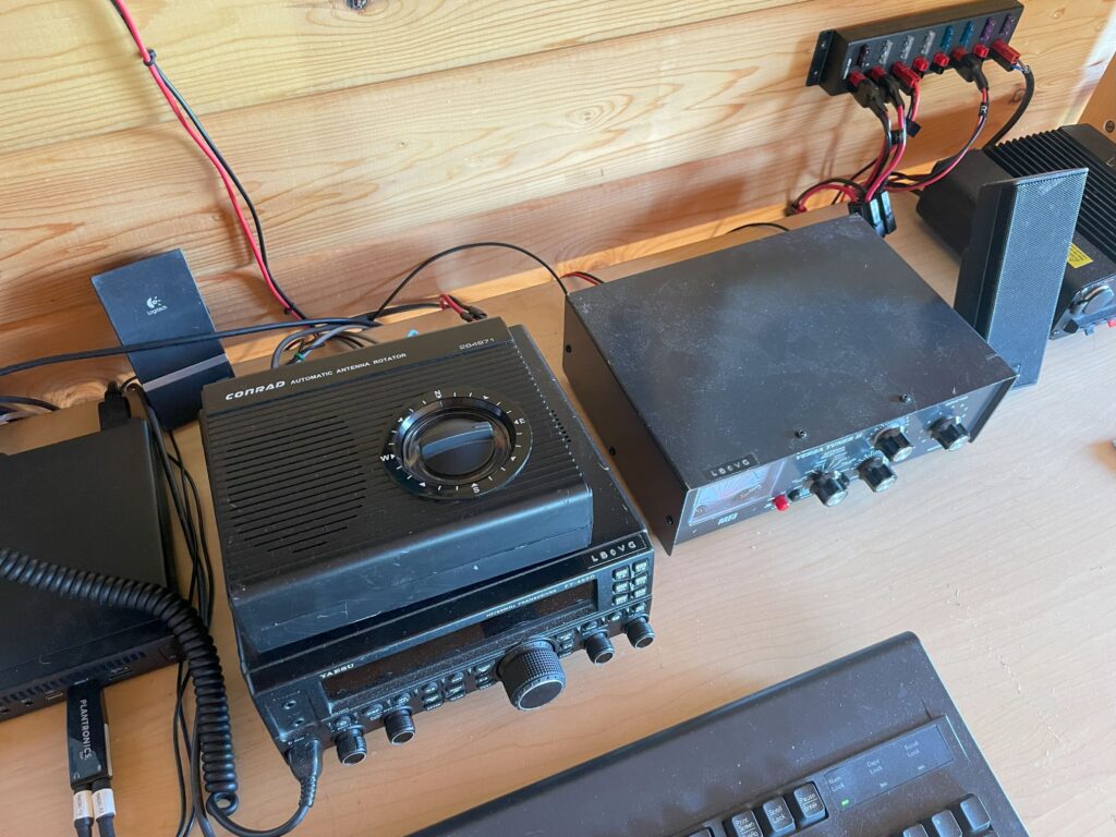
The indoor rotor control unit in the shack.
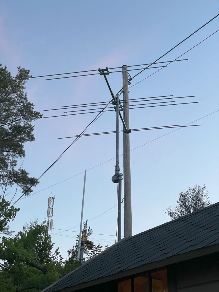
The new 6/4m yagi, mounted ontop of the Conrad rotor.

The final installation turned out quite alright, although definitely with room for improvement cable management wise. I’ll let it run for a while and see how much slack is needed for full rotor rotation, and fasten the cables probably once everything seems alright.

With the new 6/4m antenna now in the location where my 20m 5/8 vertical antenna previously resided, I had to find some other means for communicating on the 20m band. Mounting the 20m antenna at ground level seemed a bit dauting as we have pets running around the garden, as well as a lot of vegetation making it a difficult job. Since the cabin is on the slope side of a hilltop, most of the coverage would also be down south. Instead I opted to install yet another dipole antenna, this time trying my luck with a windom antenna.
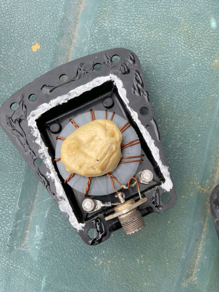
I already had a 1:4 Fritzel balun available, which seemed like a good alternative to the 1:6 balun used in some other windoms. The first step consisted of fixing the balun, as it was currently falling apart. After applying a healthy amount of glue and waterproof sealant, I think this balun will keep itself in one piece for a while. Luckily the balun itself and the internal connectors looked fine, but tighetning them before sealing the box seemed like a good idea regardless.

With a lot of help from this site, I tried narrowing down my options, especially as the total antenna length for my designated mounting location would be a challenge. I originally thought about building a Fritzel FD3 equivalent, which quickly summarized is a shortened FD4, covering just 40/20 and 10m (with options for covering 15m as well.)
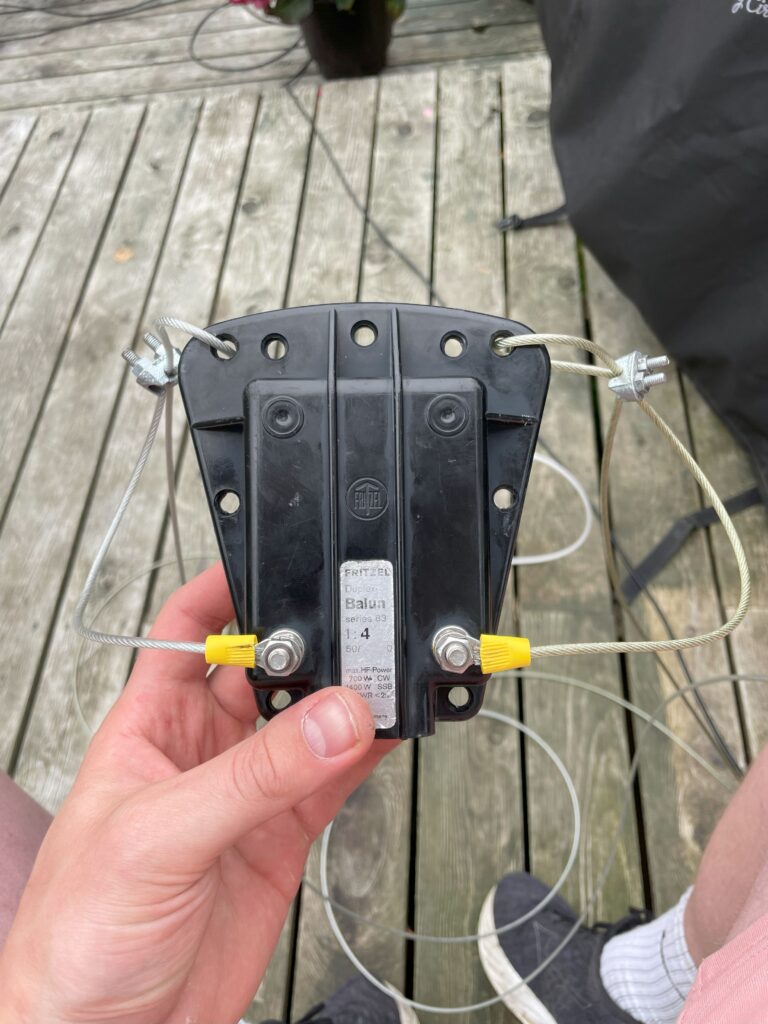
The 1:4 Fritzel Duplex balun ready to use in the windom antenna

Hooking it up with the appropriate lenghts of wire for a FD3 antenna, about 13.8m and 6.9m for the two sides, I found two things: The antenna was obviously too long, and adjusting it would definitely take some me some time. As I already had made the fastening points for the designated space, I decided to go back to the drawing board.

The windom formula is quite simple, only really differing from a dipole antenna in the ratio of wire present on either side of the balun. For a windom antenna one of the sides will be 2/3 of the total lenght of a 1/2 wavelength, while the other side will be 1/3, making up the full 1/2 wavelength in total. With this formula I decided to make a “FD2” antenna, just making 20m the lowest band and making the adjustments accordingly. In summary, this means the legs of the windom would be half the length of the FD3, which in turn is half the length of that of the FD4 windom antenna. Great!
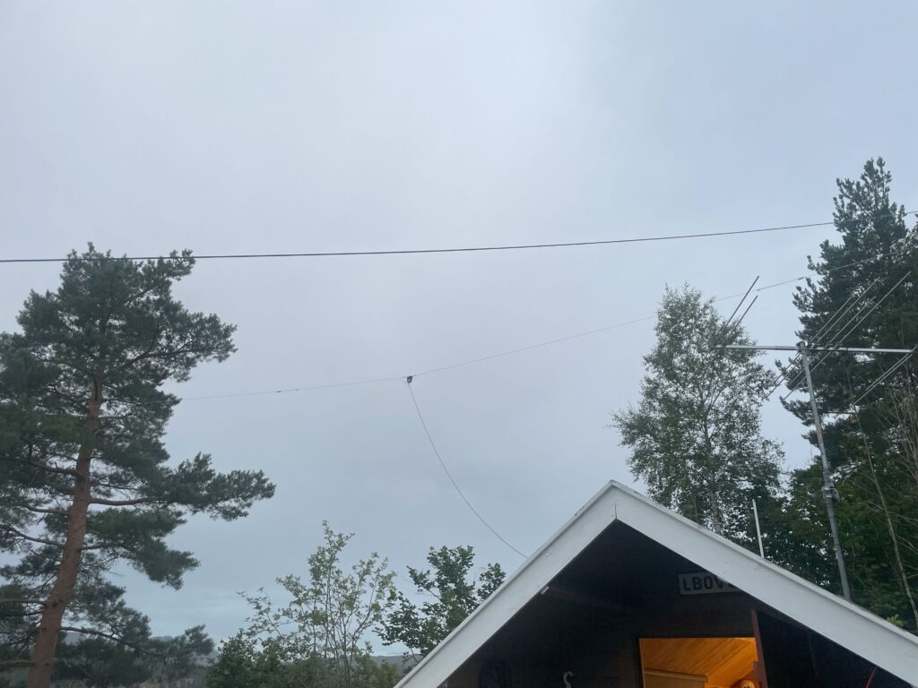
The 20m “FD2” windom-antenna.

After mounting the windom last summer it can say it works wonderfully, giving great signals on my SDR-receiver and giving great performance my station antenna too. The 6/4m-beam hasnt been used too much, but a number of 6m FT8-QSOs have been logged to verify that it works correctly. I still dont own a 4m capable transceiver yet, so a building project might be in order for me to fully test the new beam. This post was mostly written last summer, so this is just a summary to update on my current antenna setup.
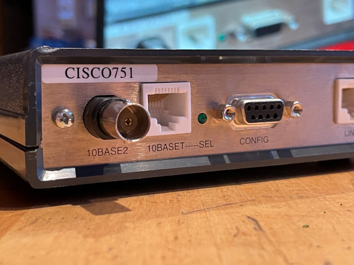
Retro networking: Cisco 751 ISDN router

In travelling home for holidays, I found myself joyfully going through my collection of old computer equpiment still piling up here.

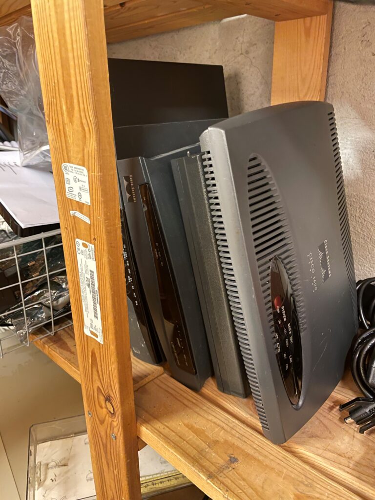
In one of the shelves I have a stack of Cisco boxes, one of which is a Cisco 751; a ISDN router with seemingly a good number of connection options for the time – 10Base2, 10BaseT and ISDN for uplink connectivity. Wondering what this unseemingly discrete box was used for, I whipped up my Google-fu and started looking up information about this thing – or so I thought.

A stack of Cisco-boxes

It seems most of the information of this thing resides in mirrors of old Cisco websites, luckily still hosted by some individuals for some unknown reason. All potential links pointing to Cisco officially are dead, and probably rightfully so since this thing is ancient.

Regardless of this, I found a old Cisco announcement of the 750 series, with its features as following:

….the Cisco 750 series is tailored fortelecommuters and small professional offices that require IP and IPXrouting over ISDN. In addition to offering ISDN remote access, the Cisco 750 series offers amodel with an external analog telephone interface to enable analog devices,such as plain old telephones (POTs), facsimile machines and modems, toshare a single ISDN Basic Rate Interface (BRI) line.

Nevertheless, I was intrigued enough to have at hand a fairly unknown router from the early 90s sporting 10Base2, as I think this would be a great gateway for my plans of a retro 10Base2 network.

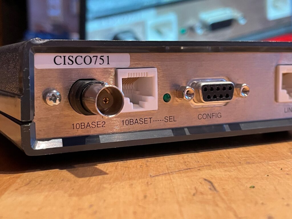
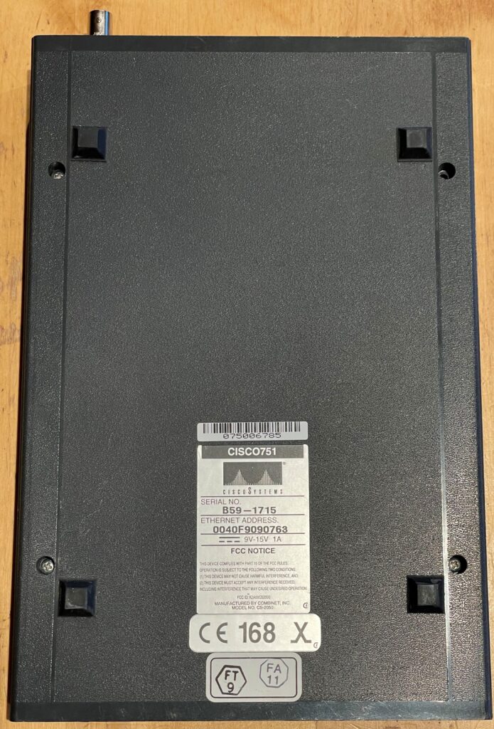
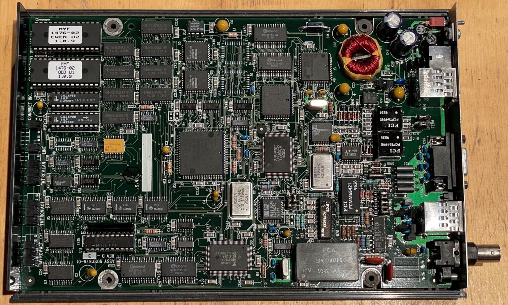
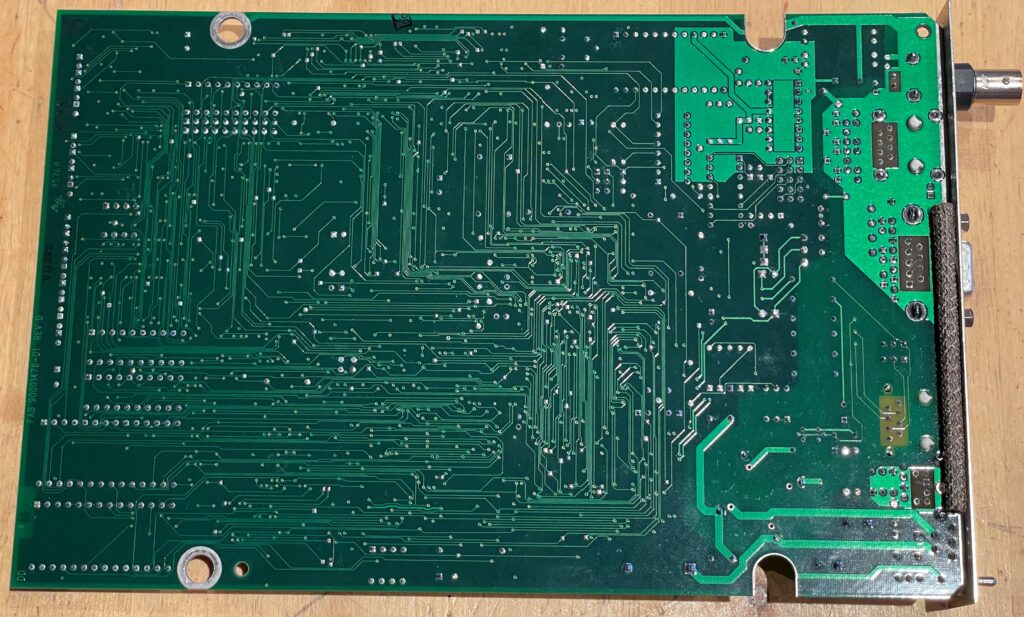
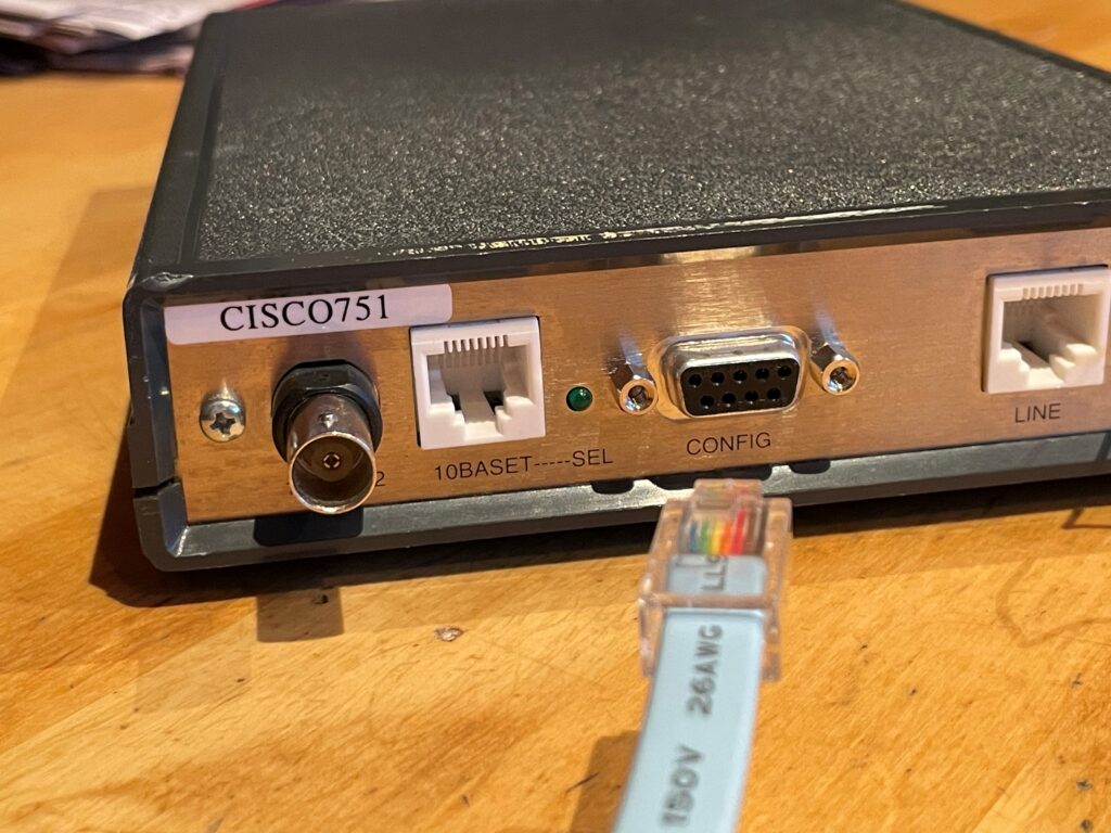
Since there are literally no pictures of the Cisco 751 online (or just a few of the 750 series at all), I here present my contribution to making the world(-wide-web) a better place:

Cisco 751 front
Cisco 751 back
Cisco 751 bottom view

Inside, the box is filled to the cram with ICs and other goodies – way before any any integrated circuits doing the heap of the work of routing traffic.

Cisco 751 board – top view
Cisco 751 board – bottom view

My first and obvious obstacle was the missing original PSU. I remember having this thing for a while, though never being able to test it with the proper equipment. To the drawing board!

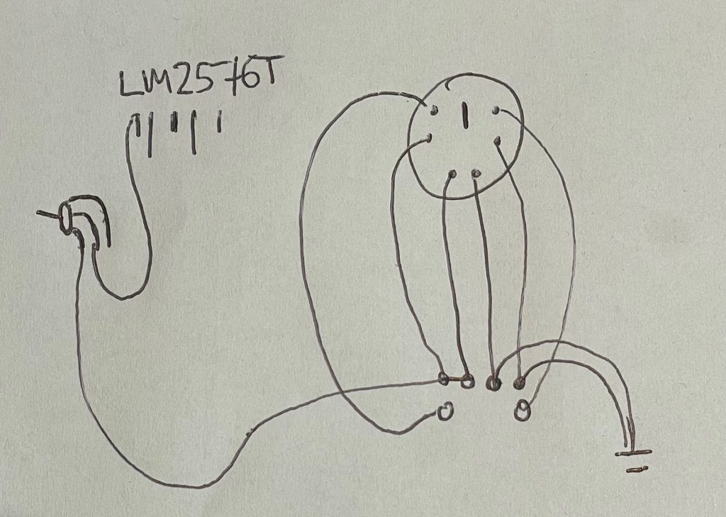
A quick drawing of the input circuit – a on/off button, the voltage regulator and the mini-DIN power connector

The input is first passed through the input switch, meaning the switch actually removes all power to the unit by switching off the regulator. The LM2576T voltage regulator generates 5V for the logic; there is another regulator inside the unit for generating the -9V from the +5V rail.

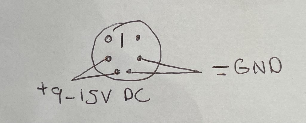
Cisco 751 PSU pinout – seen from the back of the unit

Above is a simple drawing for determining how to power the Cisco 751. There are 2 pins for GND and 2 pins for +VCC, which can be anything between 9 and 15 VDC.

Improvise, adapt, overcome!

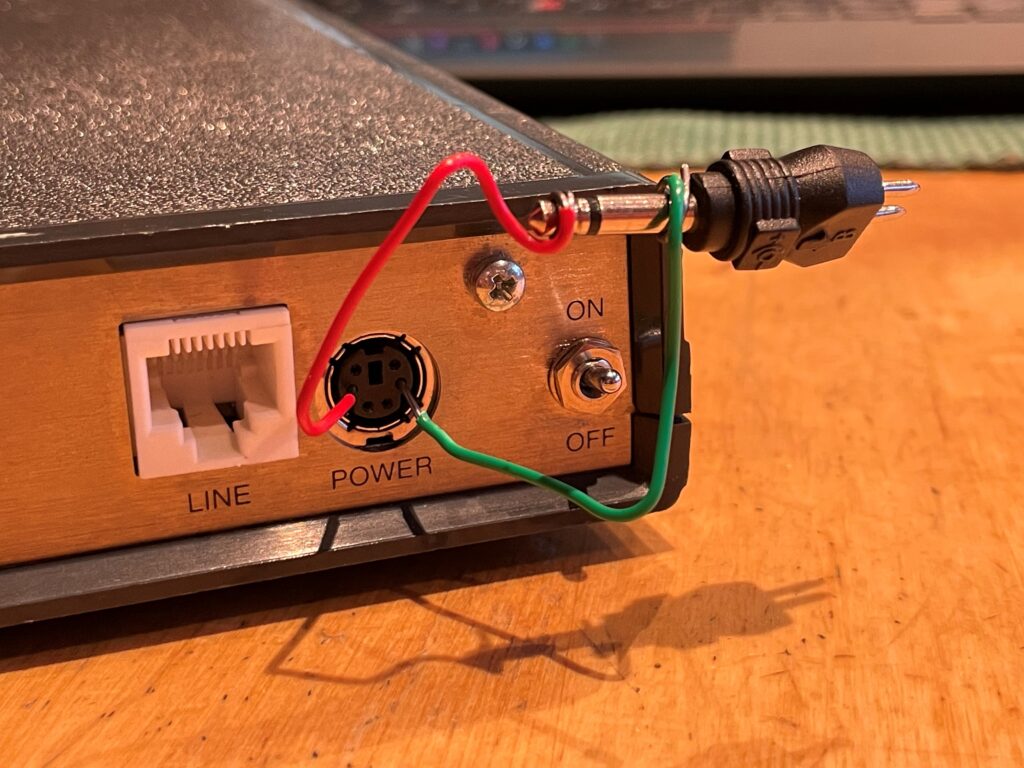
Being home for the holidays, finding the correct test equipment proved difficult and I had to make do with I found- in this instance a 3.5mm DC jack and a couple of paper clips which were carefully inserted into the DIN-plug in the back of the box. On the first power up, afraid to let the magic smoke out, I started at 9V to minimize any possible damage to the unit.

But what do you know…. it works!

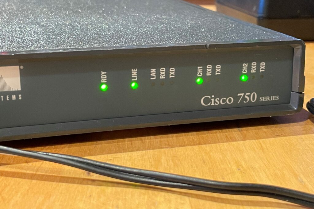
Green lights – a good thing!

The unit flashed up with green leds, starting the usual ISDN connection procedure just like it hadnt been 20 years since it was last used. Eager to find what secrets this time capsule has been hiding all these years, I grabbed my go-to Cisco serial cable from my bag to connect it to the serial port.

If I dont fit, I dont sits?

Yeah, that did not work. This thing precedes the blue-Cisco-serial-port era, sporting a standard DB9-plug. This would normally not be an issue as I have serial cables for days, but remember the part about being home for the holidays without my stuff? Yep.

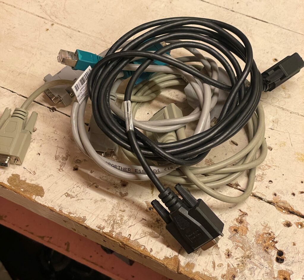
If only one of these would work…

Even though I was able to grab a hold of more serial cables than most people have lying around at home, I could not find a single one up for the task. Some were null-modem, some were a completely different proprietary pinout.

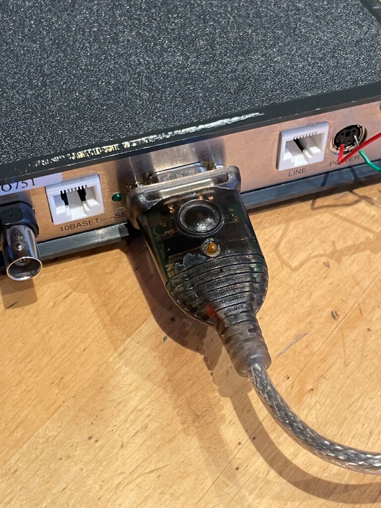
How then?

Bingo! Simply a case of unscrewing the standoffs and mashing the USB-adaptor right into the plug.

Expectedely, I was met with a password protected prompt when booting the unit. Unfortunately all my password-recovery tricks were unable to get me into this thing as it preceedes most of any Cisco hardware. Adding the fact that there is no documentation for this thing online, I decided to leave it at that at come back to it at a later point.

Making a EnGenius PoE injector

Recently I acquired a couple of EnGenius AP/p2p-bridges.

These require proprietary, passive PoE injectors, and since I didn’t want to invest any money into these, I decided to make my own.

They run of 24VDC, and utilize two of the pairs in an standard Ethernet-cable.

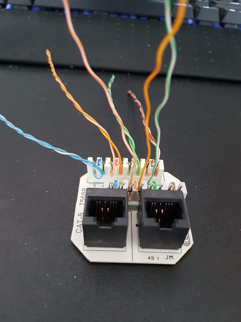
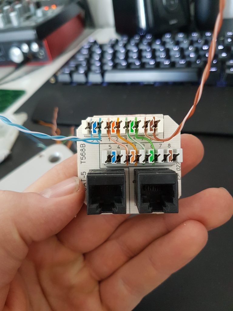
Making the injector itself wasn’t too hard. I based mine out of a double Ethernet-jack and some wire from a network cable
The jack already had some wires in it, so I simply removed the ones I didn’t need.

The orange and green pairs were used for Ethernet, as seen in the picture above. The blue and brown pairs were used to connect the power supply.

To minimize any wiring mess, I punched down short wires between the terminals for the two jacks.

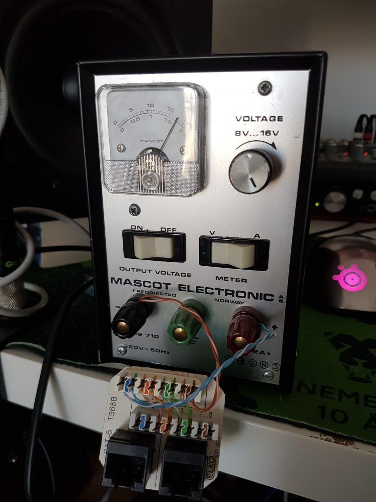
Testing the ‘PoE-injector’ with my handy bench-supply

For the PoE-jack I put in the two additional pairs (100Mbit Ethernet only requires two pairs) which supply 24V on pin 4-5 (positive) and 7-8 (negative)

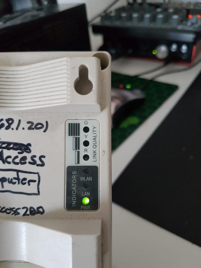
It works!

This will in theory work the same way as a EnGenius EPE-1212 or similar. Just solder a DC-jack onto the powered pairs and apply your favorite 24VDC adapter to get going.

I will try powering these with Ubiquiti passive-PoE adapters as they seem to utilize the same pairs (and the same voltage) so they might be an easy drop-in replacement for the original ones (plus you don’t need to supply your own 24V PSU!)

Update: Ubiquiti PoE-adapters (the passive ones) work just as expected as they use the same standard for powering the device. So if you have lost the original power supply you can easily just purchase one to replace it.

Reviving an old Tandberg TDV 5010 keyboard

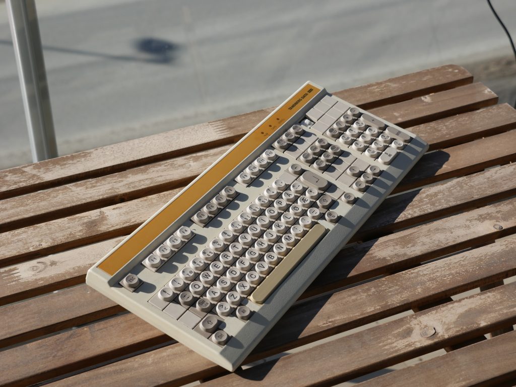
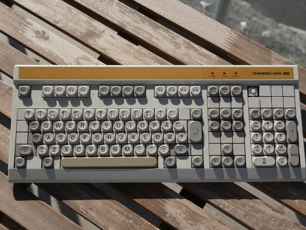
Today I finally decided to fix up the Tandberg keyboard that I’ve been holding onto for some time now.

The board in question is a Tandberg TDV 5010, part of the 50XX series. The 5010 is the only model where the surplus keys are covered by blanks.
The blanked keys still work and output random letters from the QWERTY-layout upon contact.
The other two models, the 5000 and 5020, instead have dedicated keycaps for the NOTIS text system, developed by Norsk Data.

The keyboard itself didn’t look too bad, but it had some scuff marks along with a couple of non-working keys which made it rather hard to type with.

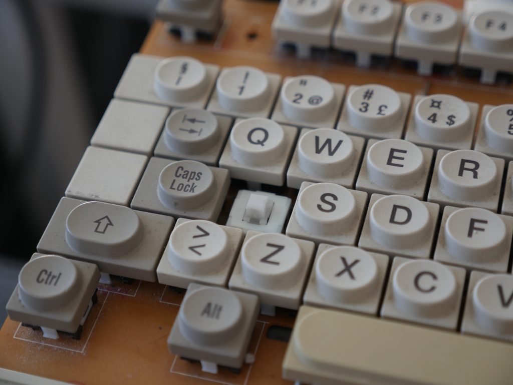
Although it appears clean from the outside, the keys hide decades worth of dust.

Yuck!

The first step was to look at the bad keys. The space-bar did not appear to function, and the culprit turned out to be a broken solder joint on the key switch.

I proceeded with scraping off some of the PCB to expose some more copper, and affixed the switch properly with hot glue. Easy!

The next key in question was the ‘A’-key. The traces connected to the keyswitch looked all good, and upon resoldering it, the key seemed to work again.
However, upon testing the keyboard I found that the key missed a lot of key presses. I swapped the switch with one of the other blanked keys, and sure enough, it worked again.

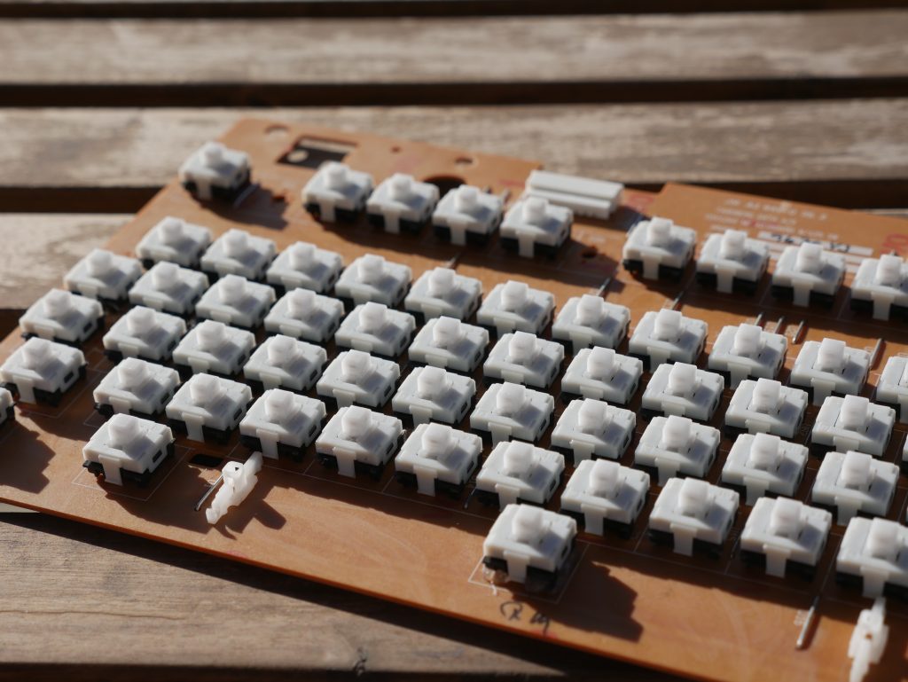
Below is a couple of pictures of the switches used in these boards, which are Siemens STB 21 switches (click the link to learn more about them)
They feel a bit like Cherry MX Brows, though with a more noticeable tactile feedback.

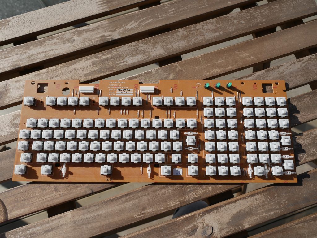
The next task was to clean the PCB itself.

After a couple of rounds with cotton swaps soaked in rubbing alcohol, the PCB now looks a lot better.
Although I could have taken the time to remove every switch and clean it thoroughly, I was happy with how it turned out with my minimal effort

The next part was cleaning the keycaps.

When I clean keyboards I like to be thorough as to remove as much dirt as I can.
To clean every key properly, I scrub them one by one with dishwasher soap.
This can really get tiresome, but the end result is worth it every time.

After scrubbing them, I rinsed off the soap using a pasta-tool (sorry, I don’t know what this thing is called)

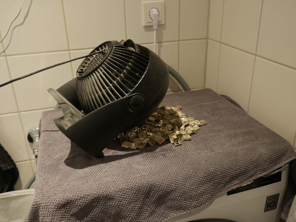
Afterwards, I put them all on a blanket to dry and pointed my fan at them. Notice the funky way of using the cable for keeping the fan at an angle.

When all the keys were dry, I carefully replaced all the keys on the PCB and assembled the keyboard back together.
The top frame was also wiped off with a grease remover, along with rubbing alcohol to remove the worst scuffs.

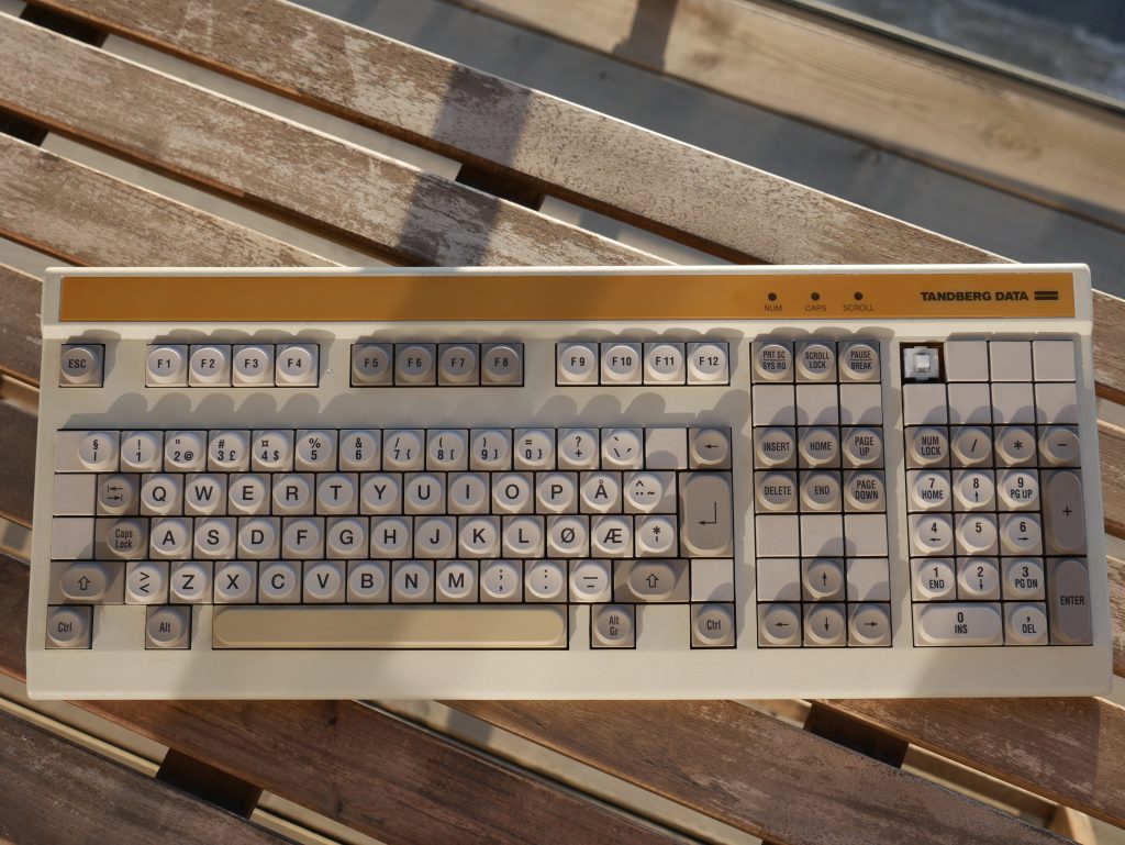
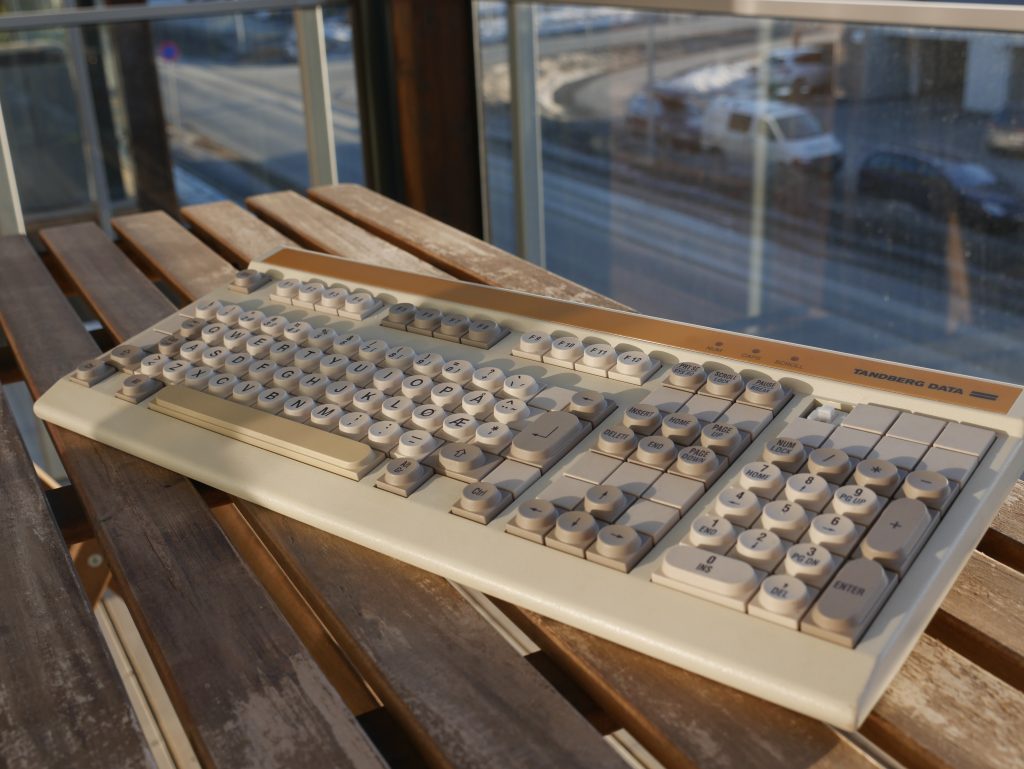
This is the end result.

Although it might not seem like much of an improvement, the keys are definitely more comfortable to type with, in addition to all the removed dirt.

I also removed some pen marks found in various places on the board (so much for writing my name on it 10 years ago)

For now, this thing can continue towards another 30 years of service (or dust collecting, who knows..?)

JX-3P button repair

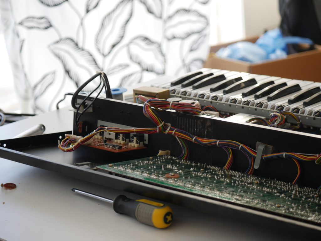
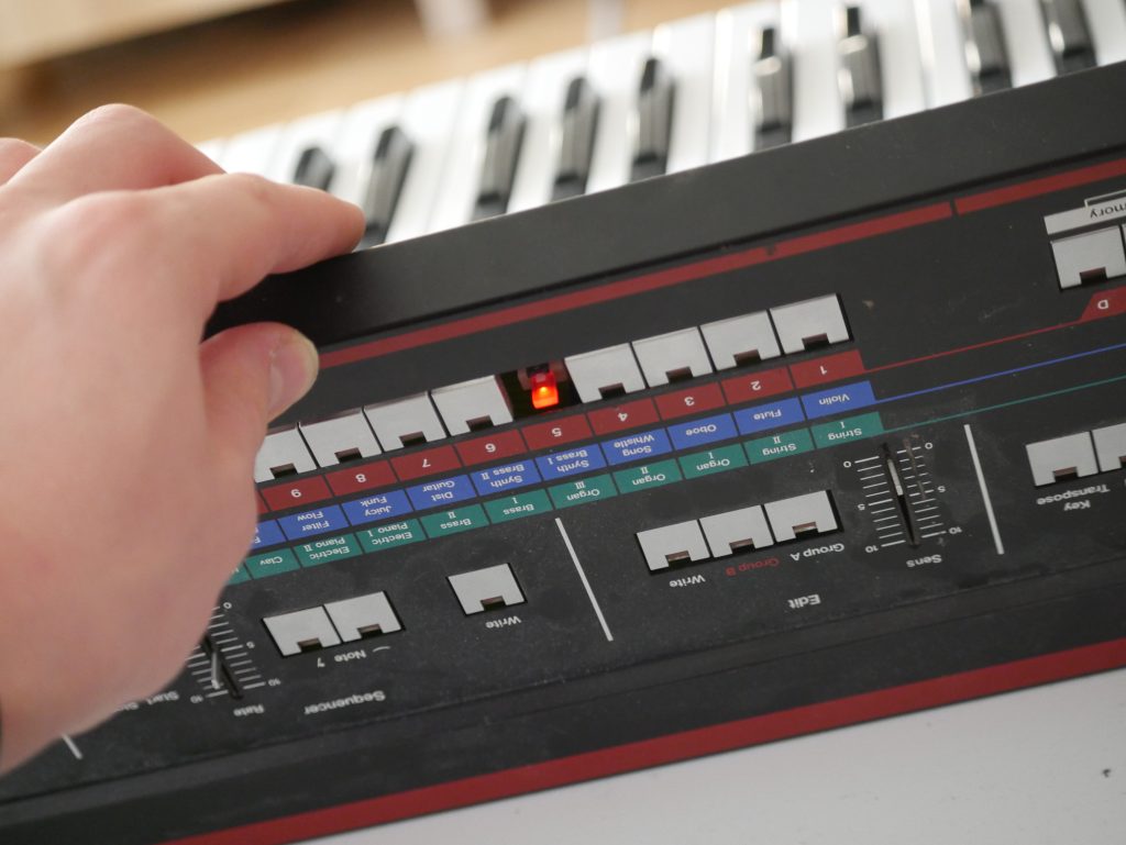
For a time now the preset “5” button on my JX-3P has not been working. I’ve been laying off this repair as I’ve had other stuff to do, but today I decided to do something about the matter.

Initially before opening the unit, I thought the button itself had simply failed. I tried measuring whilst pushing the button, but to my surprise, the multimeter beeped when measuring between the two contact points on the switch.

Next thought was that the switch was not operating correctly due to corrosion. I gave it a quick spray of some generic electronics spray, measured the button again, and then put the synth back together. Sadly the button still did not work.

Next step I did was to measure the traces going to the button. Between the button and the key-matrix, there was a diode. Upon measuring the diode, I found it to be faulty. I found another spare in my junk box, soldered it in, and crossed my fingers. Luckily that did the trick, so I put the synth back together.

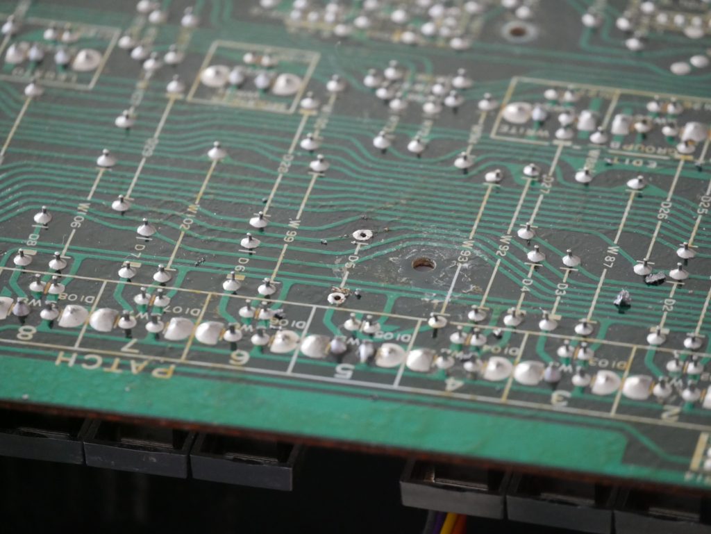
The old diode de-soldered from the board
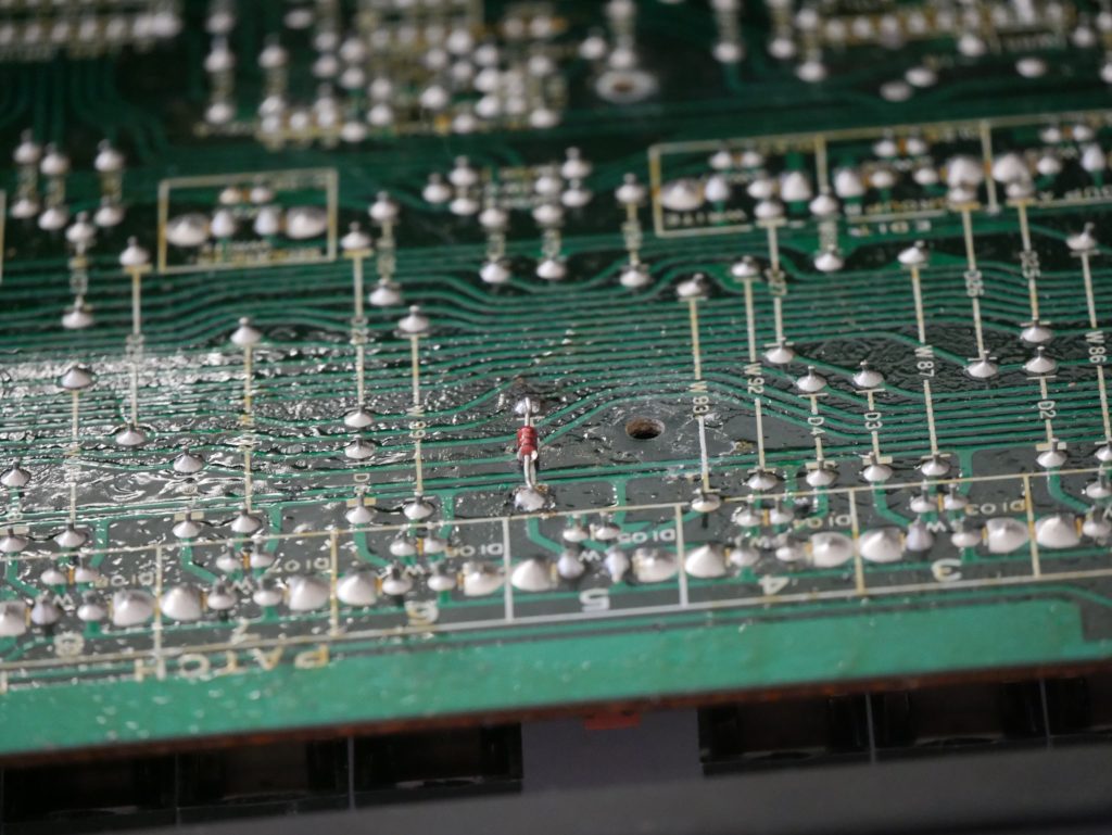
The new diode soldered onto the PCB

I had to put the new diode on the other side of the PCB as the legs were cut too short, but it fit no problem.

The “5” button is now working!

Just a quick tip for anyone who might stumble upon the same problem, as it is not necessarily the switch itself which is the culprit.