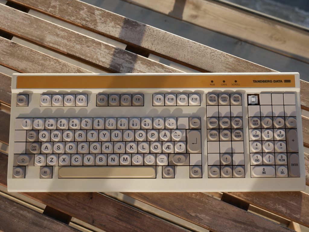
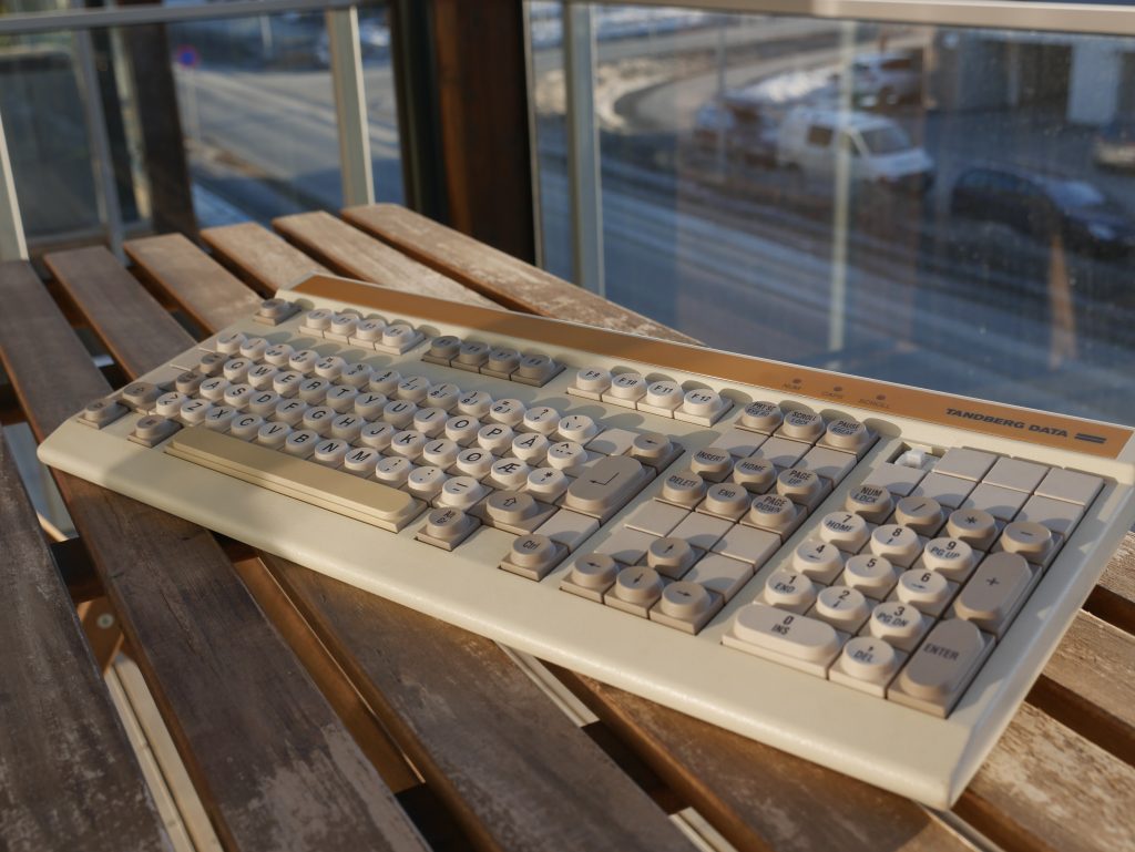
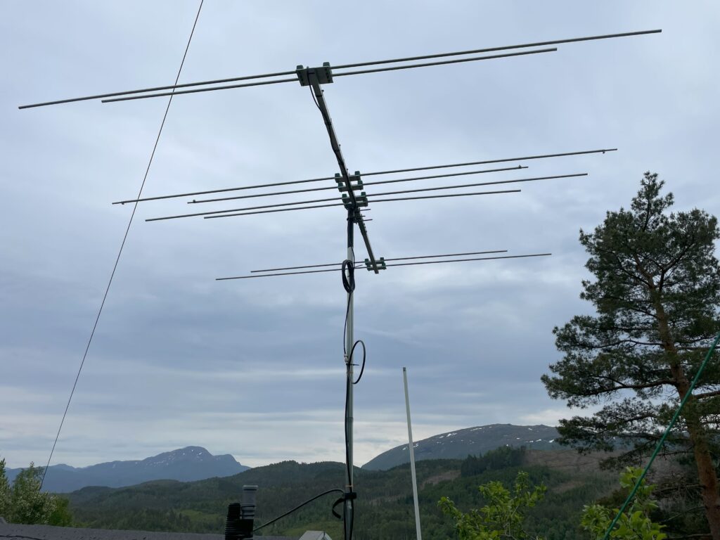
After a trip to OJ0 in 2023, I decided to buy one of the 6/4m yagi antennas used by 1UW during the expedition. My plan was to mount it up by the cabin, using the already existing pole currently being occupied by my 20m vertical antenna. This new antenna in question is the EAntenna 5070-OWA8, a 8-element yagi antenna with the elements evenly divided across the 6 and 4m band. The two bands share the same feedpoint, meaning a duplexer is required if one is to use different transceivers for the two bands.
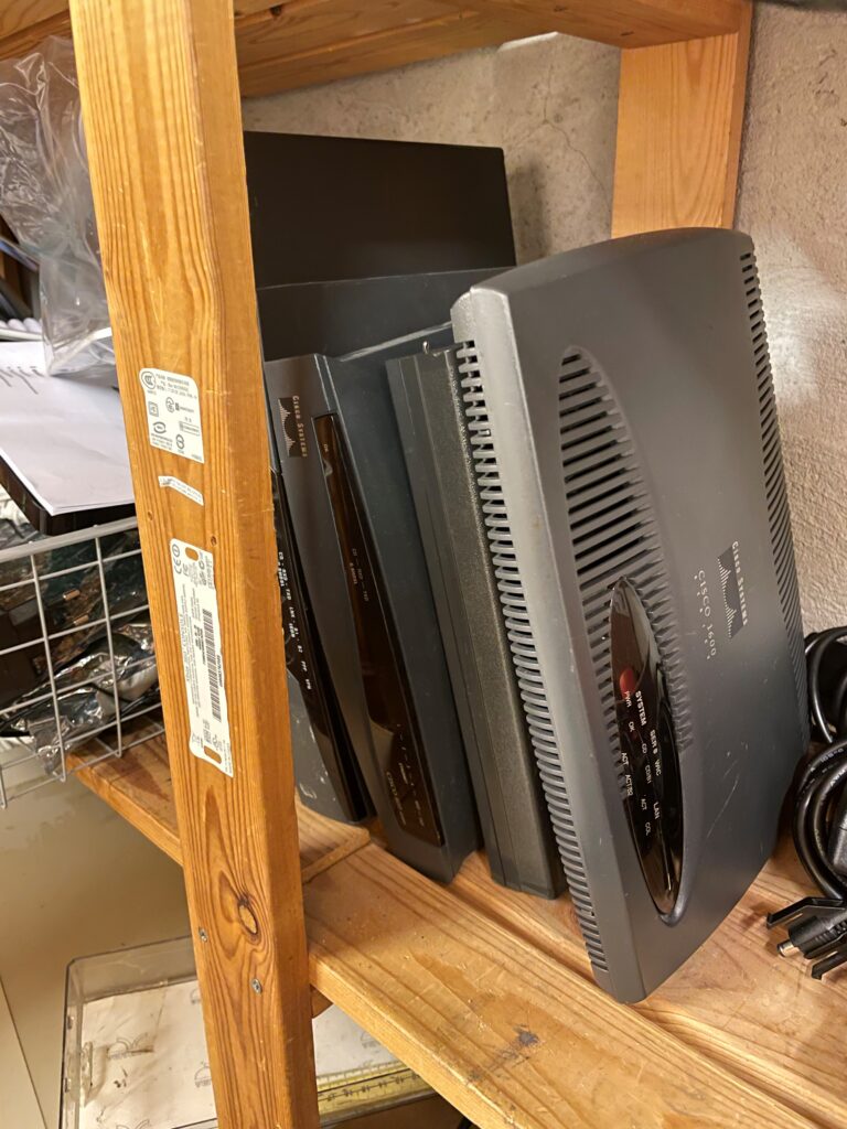
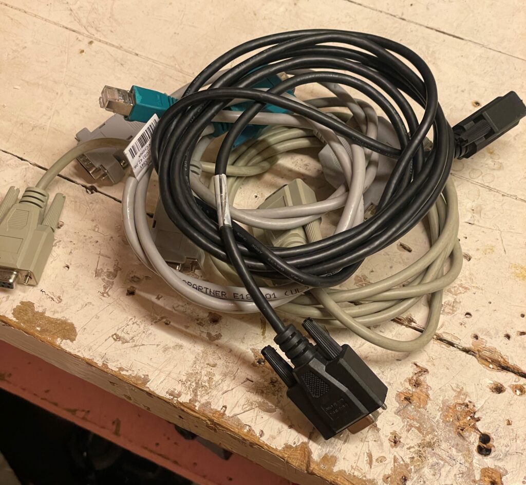
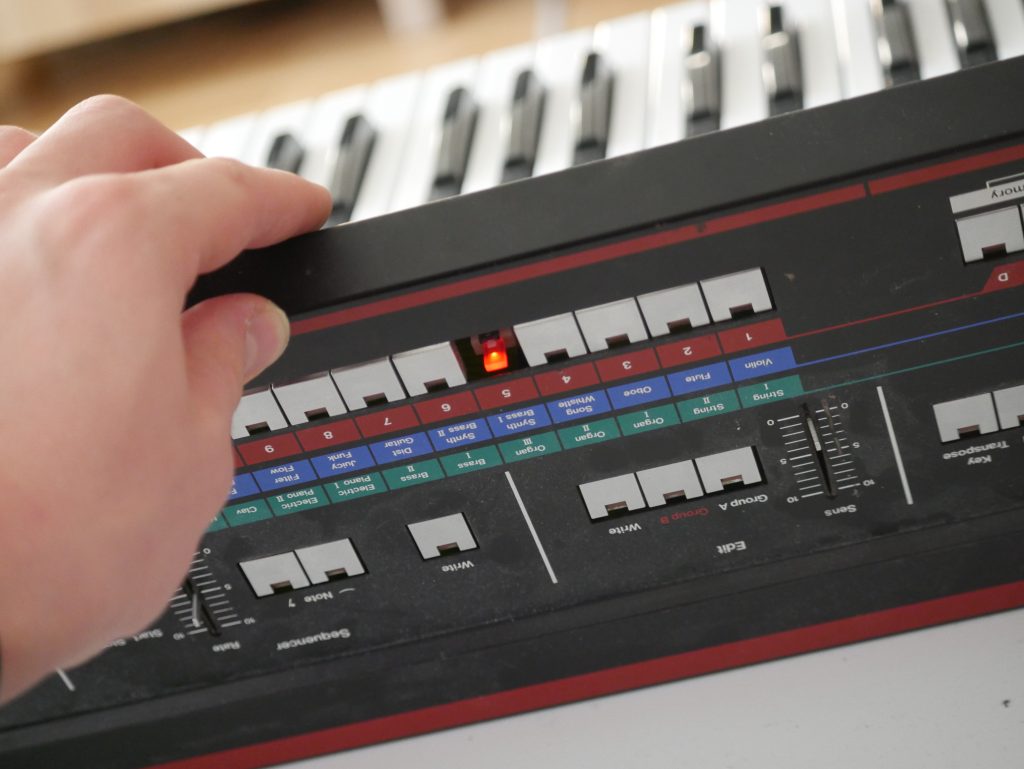
The new addition to the radio shack.
The antenna is fairly easy to install, only having to screw the elements into the center pole once the correct order has been clarified. This first install was just a proof-of-concept, confirming whether or not 6 and 4m was of any interest at this QTH. The first results were quite disappoiting, not having any luck reaching other operators using FT8. Not having the NanoVNA with me neither, I could not find what frequency it was currently tuned for. For now, the antenna was at least mounted up and hopefully only minor adjustments were required to make it operable.
During my recent visit, I found that I had put the feed cable across the center pole, and not straight down like pictured in other installs online. As this is fairly plug-and-play antenna, I immediately thought for that to cause some disruption to the antenna.
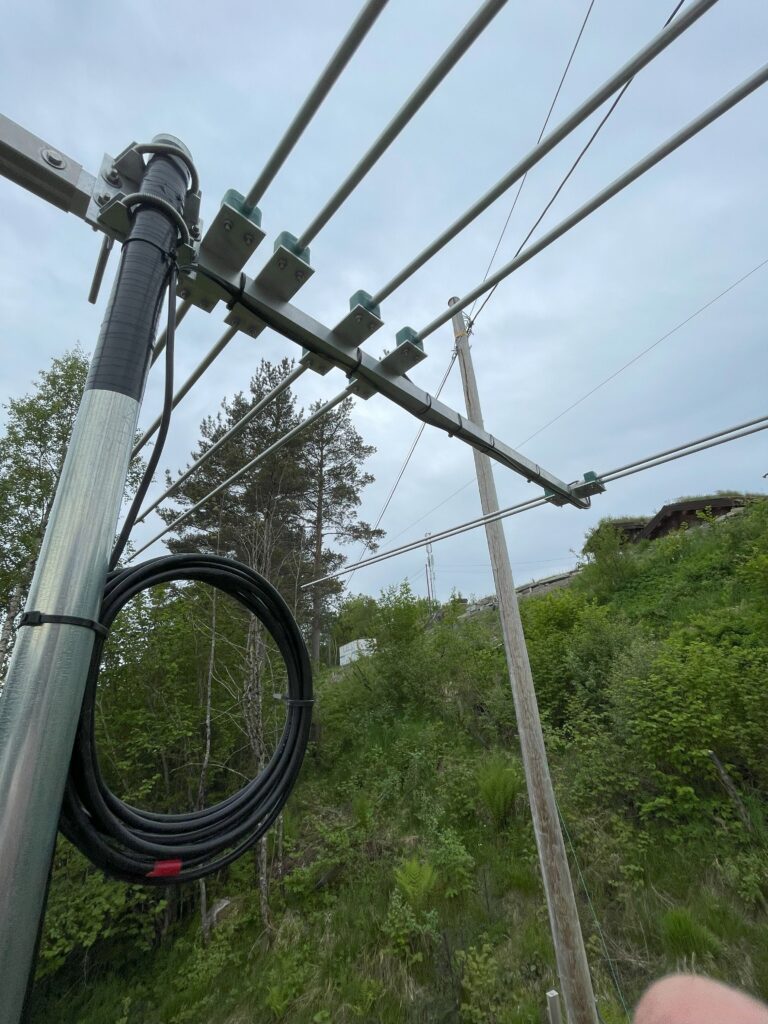
The first attempt at installing the EAntenna-yagi, with the wire going over and under the center rod, and the cable coiled up quite a lot of turns!
Another quite obvious culprit was the tuning of the driven elements for 6 and 4m, which has a innter tube allowing for a limted adjustments. As this antenna was used quite close to a metallic roof last time, the move to its new QTH could definitely call for some adjustments. After moving the cabling and tinkering with the adjustable elements, the antenna showed a much more promising SWR measurement, with the center frequency at approx 50.300Mhz.
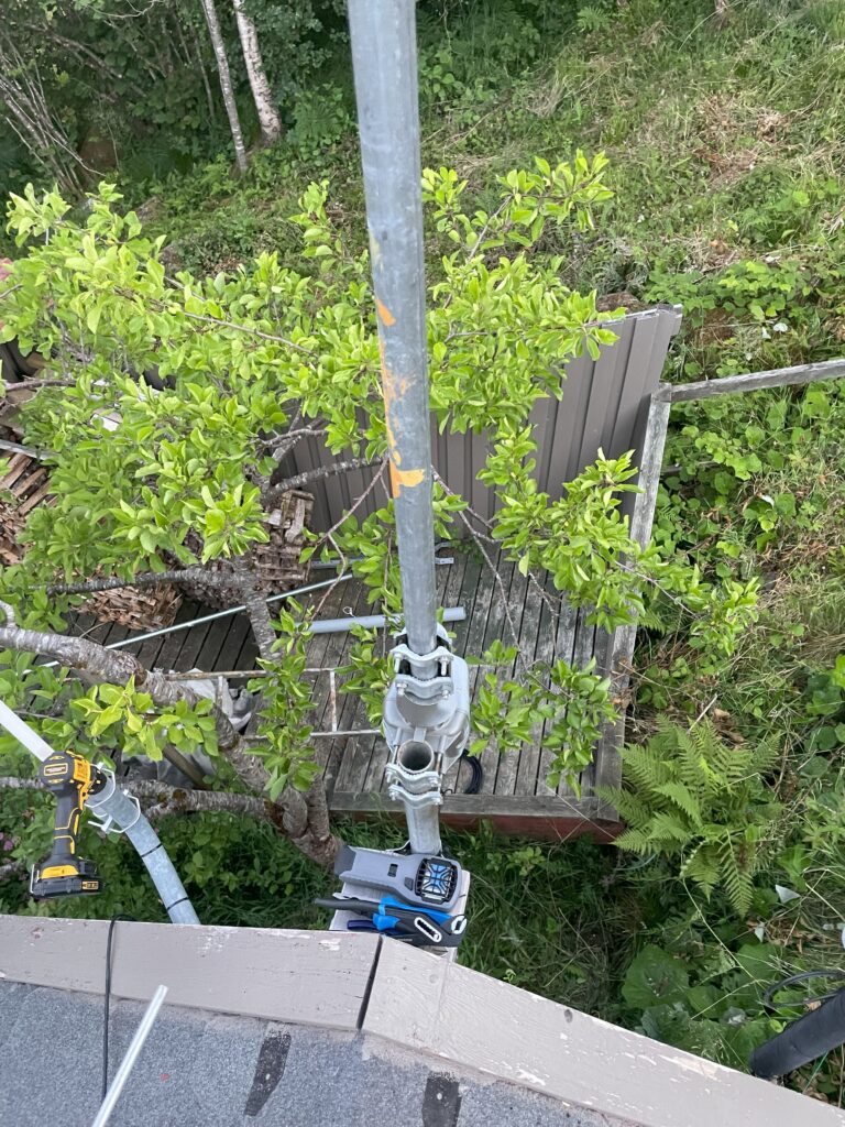
Doing mast work alone, the available mast attachment is handy as a parking spot for your equipement. Notice the mosquito repeller right below the rotor.
Next came the time to install the antenna rotor, which I had also previously used at OJ0 with good results. The antenna rotor is quite simple, consiting of a 3-wire controller and the outdoor rotor-unit itself. The rotor is Conrad 284971, though with the same controller also known under the name HyGain AR-303X. As the old mast consisted of two 1.5m mast rods that had been irreversibly put together (by design, of course), I had to find some other rods. Luckily I had a heavy-duty steel rod that I once received from a friend, plus another one of the light-weight 1.5m aluminum rods readily available. The former was placed on the bottom, with the lighter one placed on top of the rotor for the antenna mount.
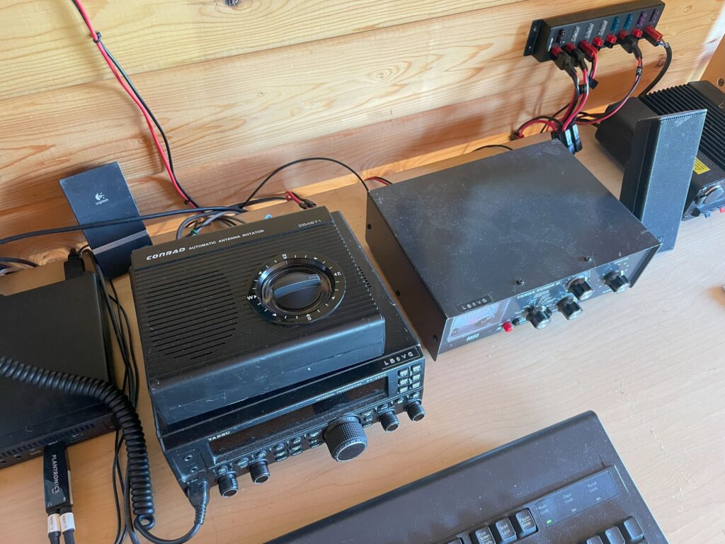
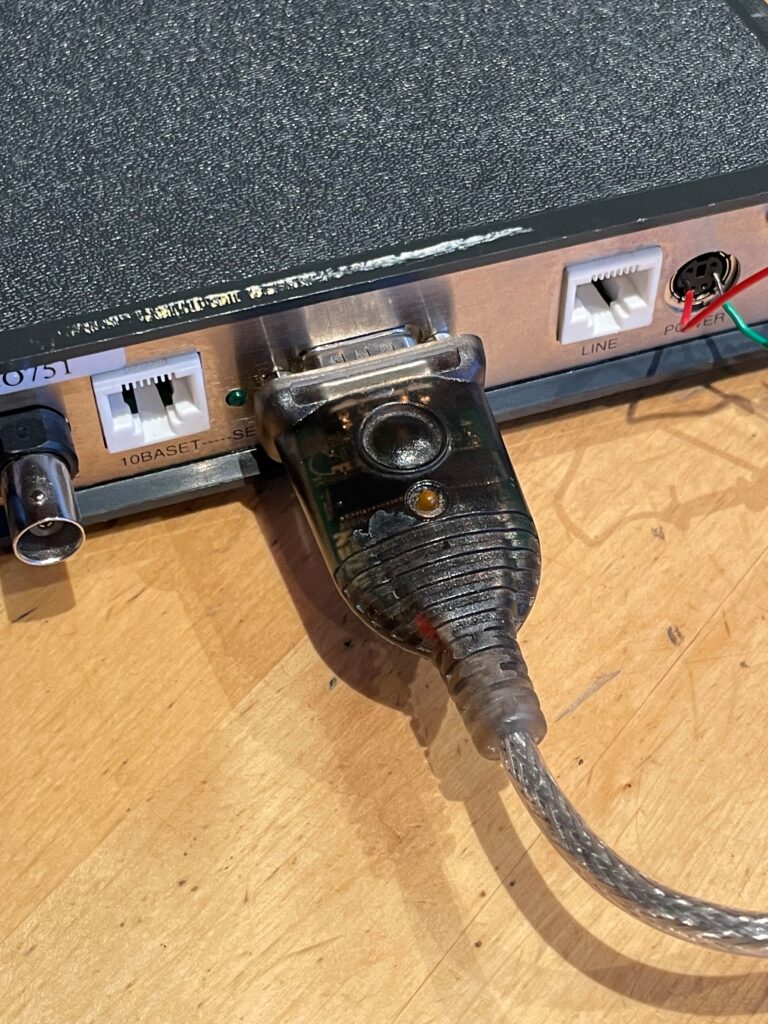
The indoor rotor control unit in the shack.
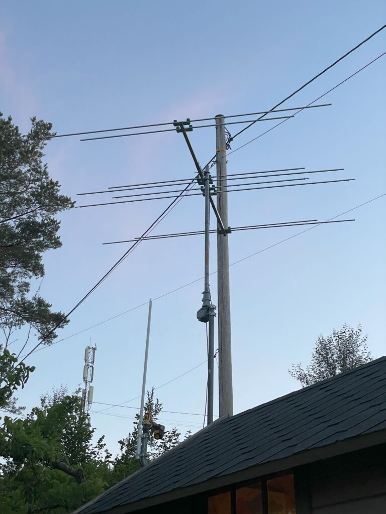
The new 6/4m yagi, mounted ontop of the Conrad rotor.
The final installation turned out quite alright, although definitely with room for improvement cable management wise. I’ll let it run for a while and see how much slack is needed for full rotor rotation, and fasten the cables probably once everything seems alright.
With the new 6/4m antenna now in the location where my 20m 5/8 vertical antenna previously resided, I had to find some other means for communicating on the 20m band. Mounting the 20m antenna at ground level seemed a bit dauting as we have pets running around the garden, as well as a lot of vegetation making it a difficult job. Since the cabin is on the slope side of a hilltop, most of the coverage would also be down south. Instead I opted to install yet another dipole antenna, this time trying my luck with a windom antenna.
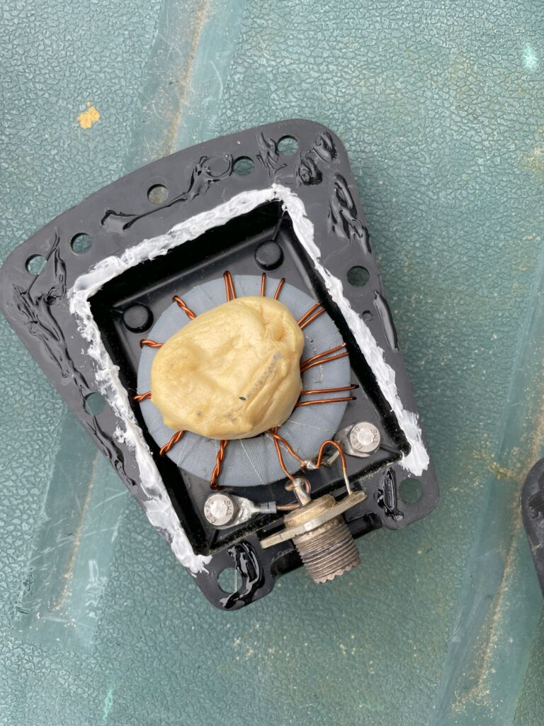
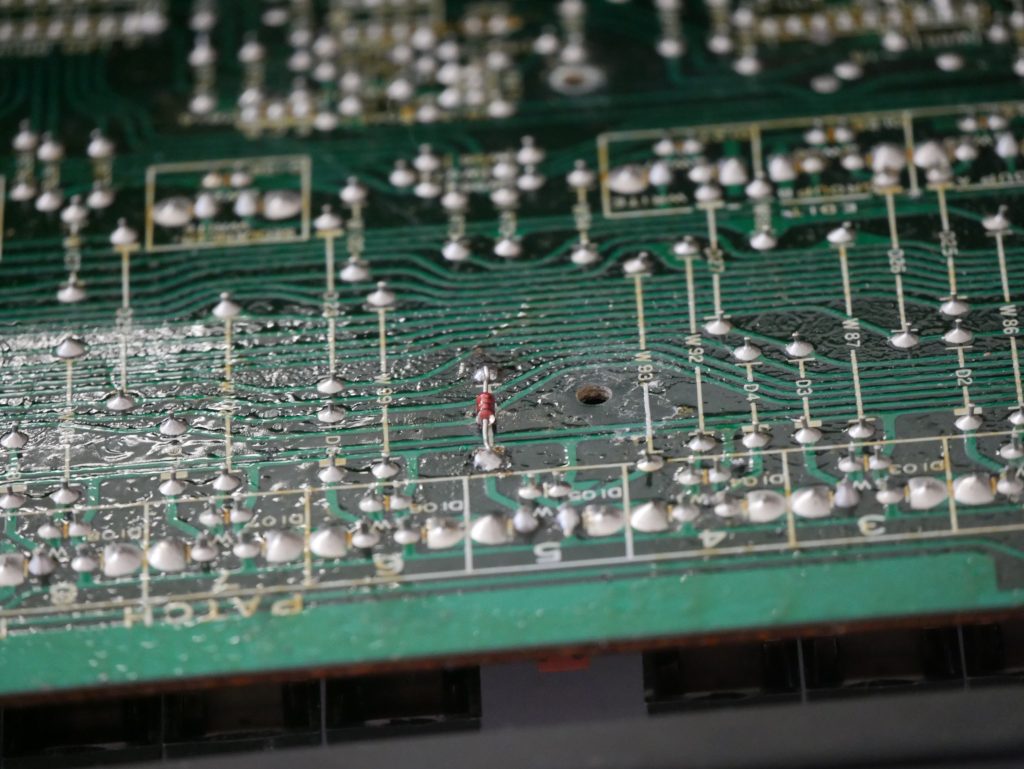
I already had a 1:4 Fritzel balun available, which seemed like a good alternative to the 1:6 balun used in some other windoms. The first step consisted of fixing the balun, as it was currently falling apart. After applying a healthy amount of glue and waterproof sealant, I think this balun will keep itself in one piece for a while. Luckily the balun itself and the internal connectors looked fine, but tighetning them before sealing the box seemed like a good idea regardless.
With a lot of help from this site, I tried narrowing down my options, especially as the total antenna length for my designated mounting location would be a challenge. I originally thought about building a Fritzel FD3 equivalent, which quickly summarized is a shortened FD4, covering just 40/20 and 10m (with options for covering 15m as well.)
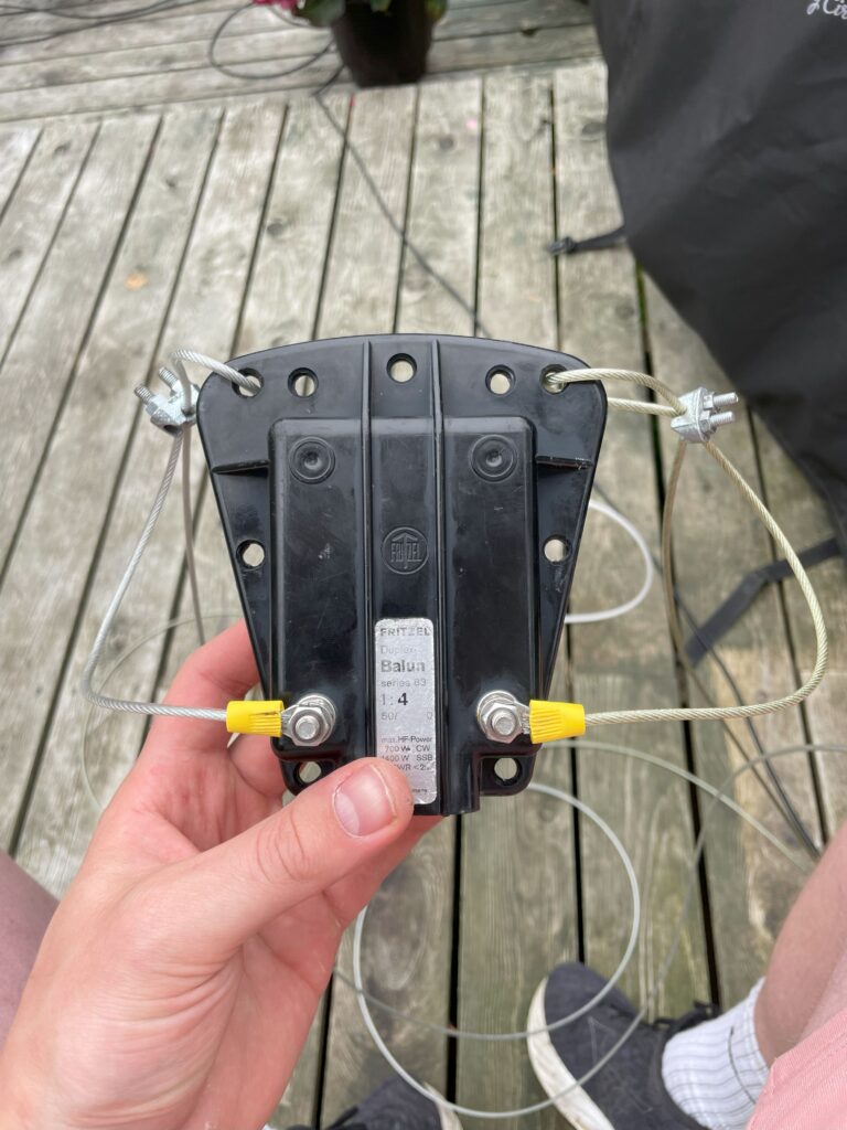
The 1:4 Fritzel Duplex balun ready to use in the windom antenna
Hooking it up with the appropriate lenghts of wire for a FD3 antenna, about 13.8m and 6.9m for the two sides, I found two things: The antenna was obviously too long, and adjusting it would definitely take some me some time. As I already had made the fastening points for the designated space, I decided to go back to the drawing board.
The windom formula is quite simple, only really differing from a dipole antenna in the ratio of wire present on either side of the balun. For a windom antenna one of the sides will be 2/3 of the total lenght of a 1/2 wavelength, while the other side will be 1/3, making up the full 1/2 wavelength in total. With this formula I decided to make a “FD2” antenna, just making 20m the lowest band and making the adjustments accordingly. In summary, this means the legs of the windom would be half the length of the FD3, which in turn is half the length of that of the FD4 windom antenna. Great!
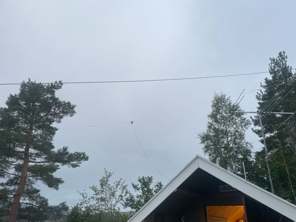
The 20m “FD2” windom-antenna.
After mounting the windom last summer it can say it works wonderfully, giving great signals on my SDR-receiver and giving great performance my station antenna too. The 6/4m-beam hasnt been used too much, but a number of 6m FT8-QSOs have been logged to verify that it works correctly. I still dont own a 4m capable transceiver yet, so a building project might be in order for me to fully test the new beam. This post was mostly written last summer, so this is just a summary to update on my current antenna setup.