Making a EnGenius PoE injector

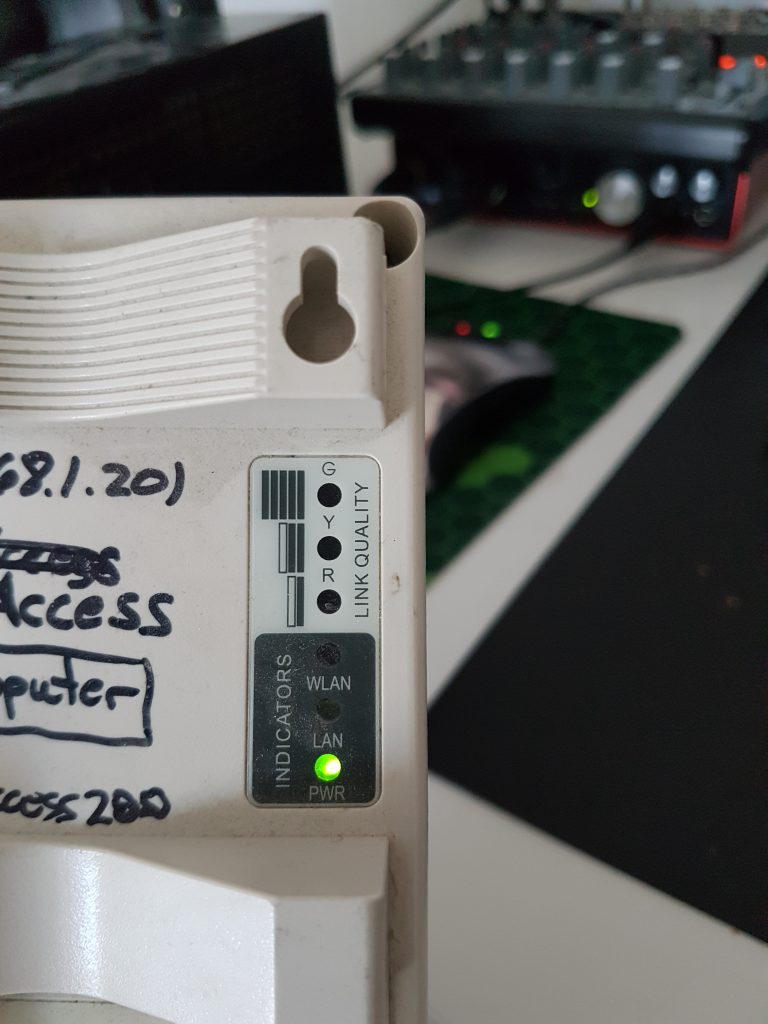
Recently I acquired a couple of EnGenius AP/p2p-bridges.

These require proprietary, passive PoE injectors, and since I didn’t want to invest any money into these, I decided to make my own.

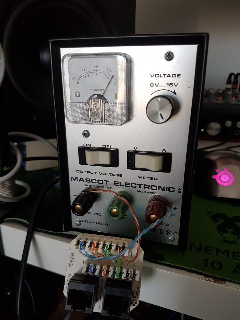
They run of 24VDC, and utilize two of the pairs in an standard Ethernet-cable.

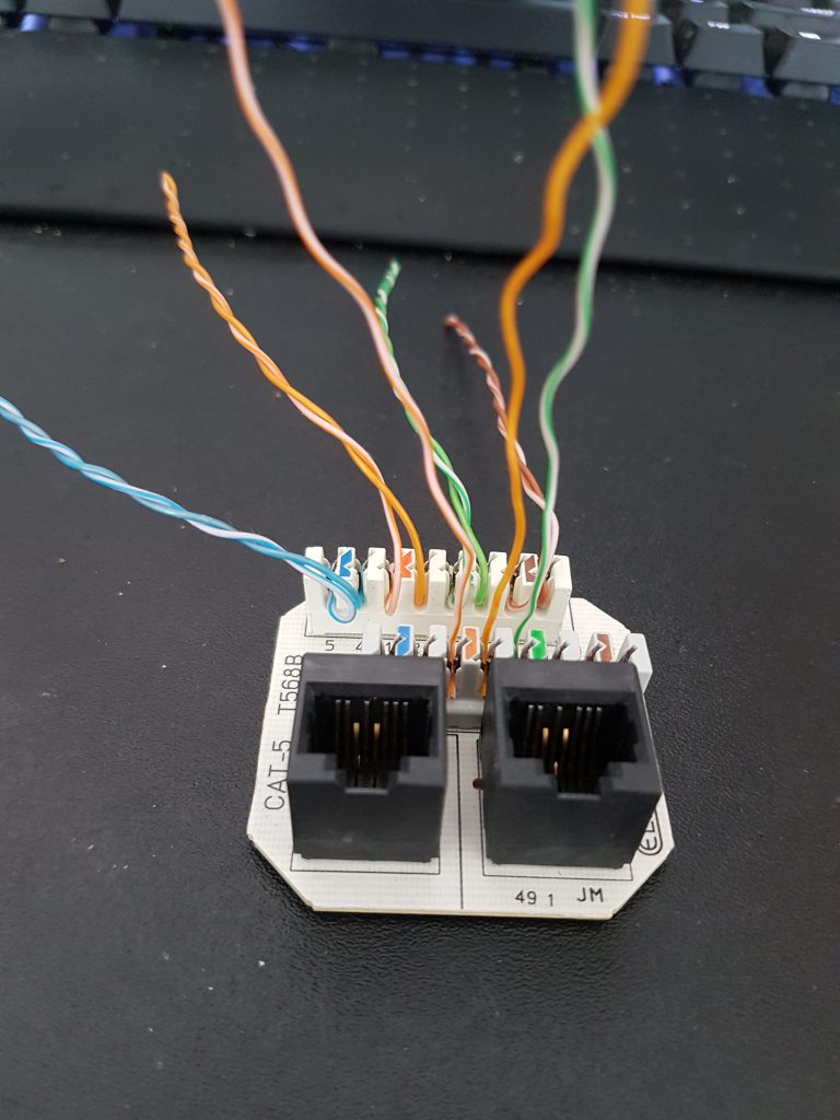
Making the injector itself wasn’t too hard. I based mine out of a double Ethernet-jack and some wire from a network cable
The jack already had some wires in it, so I simply removed the ones I didn’t need.

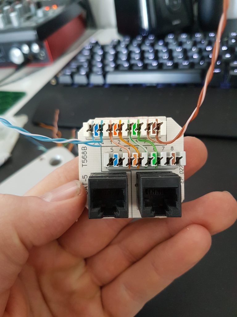
The orange and green pairs were used for Ethernet, as seen in the picture above. The blue and brown pairs were used to connect the power supply.

To minimize any wiring mess, I punched down short wires between the terminals for the two jacks.

Testing the ‘PoE-injector’ with my handy bench-supply

For the PoE-jack I put in the two additional pairs (100Mbit Ethernet only requires two pairs) which supply 24V on pin 4-5 (positive) and 7-8 (negative)

It works!

This will in theory work the same way as a EnGenius EPE-1212 or similar. Just solder a DC-jack onto the powered pairs and apply your favorite 24VDC adapter to get going.

I will try powering these with Ubiquiti passive-PoE adapters as they seem to utilize the same pairs (and the same voltage) so they might be an easy drop-in replacement for the original ones (plus you don’t need to supply your own 24V PSU!)

Update: Ubiquiti PoE-adapters (the passive ones) work just as expected as they use the same standard for powering the device. So if you have lost the original power supply you can easily just purchase one to replace it.

Reviving an old Tandberg TDV 5010 keyboard

Today I finally decided to fix up the Tandberg keyboard that I’ve been holding onto for some time now.

The board in question is a Tandberg TDV 5010, part of the 50XX series. The 5010 is the only model where the surplus keys are covered by blanks.
The blanked keys still work and output random letters from the QWERTY-layout upon contact.
The other two models, the 5000 and 5020, instead have dedicated keycaps for the NOTIS text system, developed by Norsk Data.

The keyboard itself didn’t look too bad, but it had some scuff marks along with a couple of non-working keys which made it rather hard to type with.

Although it appears clean from the outside, the keys hide decades worth of dust.

Yuck!

The first step was to look at the bad keys. The space-bar did not appear to function, and the culprit turned out to be a broken solder joint on the key switch.

I proceeded with scraping off some of the PCB to expose some more copper, and affixed the switch properly with hot glue. Easy!

The next key in question was the ‘A’-key. The traces connected to the keyswitch looked all good, and upon resoldering it, the key seemed to work again.
However, upon testing the keyboard I found that the key missed a lot of key presses. I swapped the switch with one of the other blanked keys, and sure enough, it worked again.

Below is a couple of pictures of the switches used in these boards, which are Siemens STB 21 switches (click the link to learn more about them)
They feel a bit like Cherry MX Brows, though with a more noticeable tactile feedback.

The next task was to clean the PCB itself.

After a couple of rounds with cotton swaps soaked in rubbing alcohol, the PCB now looks a lot better.
Although I could have taken the time to remove every switch and clean it thoroughly, I was happy with how it turned out with my minimal effort

The next part was cleaning the keycaps.

When I clean keyboards I like to be thorough as to remove as much dirt as I can.
To clean every key properly, I scrub them one by one with dishwasher soap.
This can really get tiresome, but the end result is worth it every time.

After scrubbing them, I rinsed off the soap using a pasta-tool (sorry, I don’t know what this thing is called)

Afterwards, I put them all on a blanket to dry and pointed my fan at them. Notice the funky way of using the cable for keeping the fan at an angle.

When all the keys were dry, I carefully replaced all the keys on the PCB and assembled the keyboard back together.
The top frame was also wiped off with a grease remover, along with rubbing alcohol to remove the worst scuffs.

This is the end result.

Although it might not seem like much of an improvement, the keys are definitely more comfortable to type with, in addition to all the removed dirt.

I also removed some pen marks found in various places on the board (so much for writing my name on it 10 years ago)

For now, this thing can continue towards another 30 years of service (or dust collecting, who knows..?)

JX-3P button repair

For a time now the preset “5” button on my JX-3P has not been working. I’ve been laying off this repair as I’ve had other stuff to do, but today I decided to do something about the matter.

Initially before opening the unit, I thought the button itself had simply failed. I tried measuring whilst pushing the button, but to my surprise, the multimeter beeped when measuring between the two contact points on the switch.

Next thought was that the switch was not operating correctly due to corrosion. I gave it a quick spray of some generic electronics spray, measured the button again, and then put the synth back together. Sadly the button still did not work.

Next step I did was to measure the traces going to the button. Between the button and the key-matrix, there was a diode. Upon measuring the diode, I found it to be faulty. I found another spare in my junk box, soldered it in, and crossed my fingers. Luckily that did the trick, so I put the synth back together.

The old diode de-soldered from the board
The new diode soldered onto the PCB

I had to put the new diode on the other side of the PCB as the legs were cut too short, but it fit no problem.

The “5” button is now working!

Just a quick tip for anyone who might stumble upon the same problem, as it is not necessarily the switch itself which is the culprit.