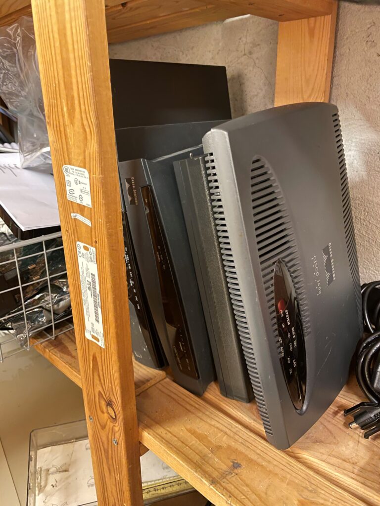
In travelling home for holidays, I found myself joyfully going through my collection of old computer equpiment still piling up here.
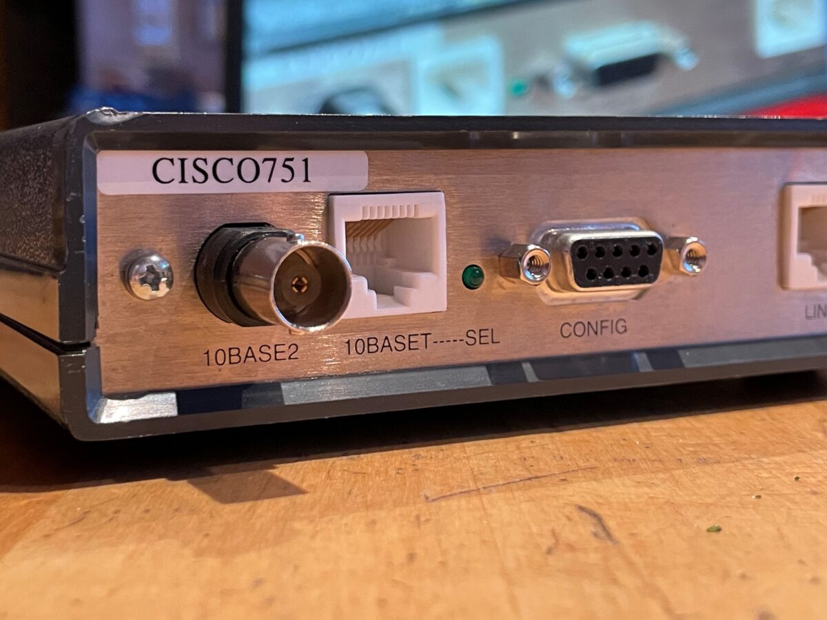
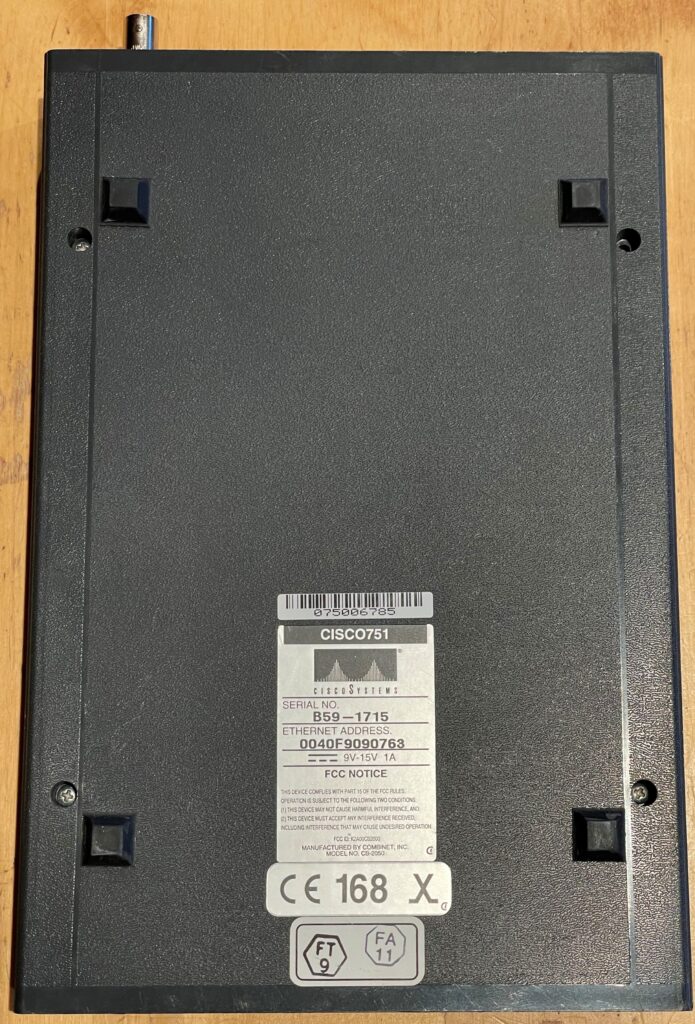
In one of the shelves I have a stack of Cisco boxes, one of which is a Cisco 751; a ISDN router with seemingly a good number of connection options for the time – 10Base2, 10BaseT and ISDN for uplink connectivity. Wondering what this unseemingly discrete box was used for, I whipped up my Google-fu and started looking up information about this thing – or so I thought.
It seems most of the information of this thing resides in mirrors of old Cisco websites, luckily still hosted by some individuals for some unknown reason. All potential links pointing to Cisco officially are dead, and probably rightfully so since this thing is ancient.
Regardless of this, I found a old Cisco announcement of the 750 series, with its features as following:
….the Cisco 750 series is tailored fortelecommuters and small professional offices that require IP and IPXrouting over ISDN. In addition to offering ISDN remote access, the Cisco 750 series offers amodel with an external analog telephone interface to enable analog devices,such as plain old telephones (POTs), facsimile machines and modems, toshare a single ISDN Basic Rate Interface (BRI) line.
Nevertheless, I was intrigued enough to have at hand a fairly unknown router from the early 90s sporting 10Base2, as I think this would be a great gateway for my plans of a retro 10Base2 network.

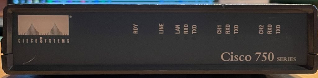
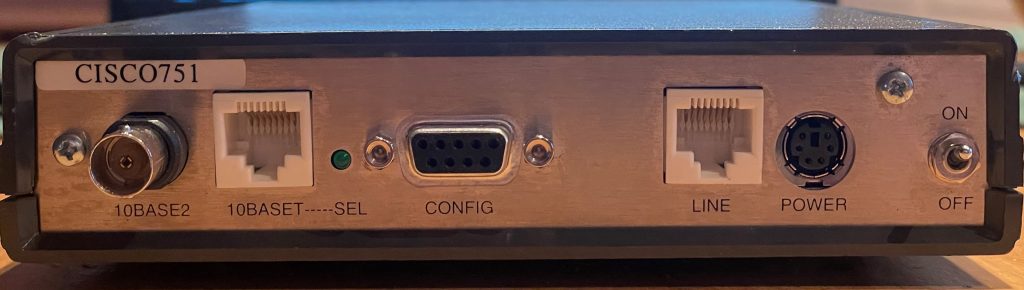
Since there are literally no pictures of the Cisco 751 online (or just a few of the 750 series at all), I here present my contribution to making the world(-wide-web) a better place:
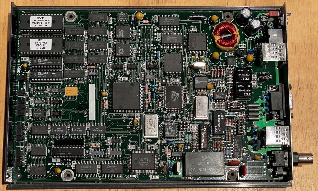
Inside, the box is filled to the cram with ICs and other goodies – way before any any integrated circuits doing the heap of the work of routing traffic.
My first and obvious obstacle was the missing original PSU. I remember having this thing for a while, though never being able to test it with the proper equipment. To the drawing board!
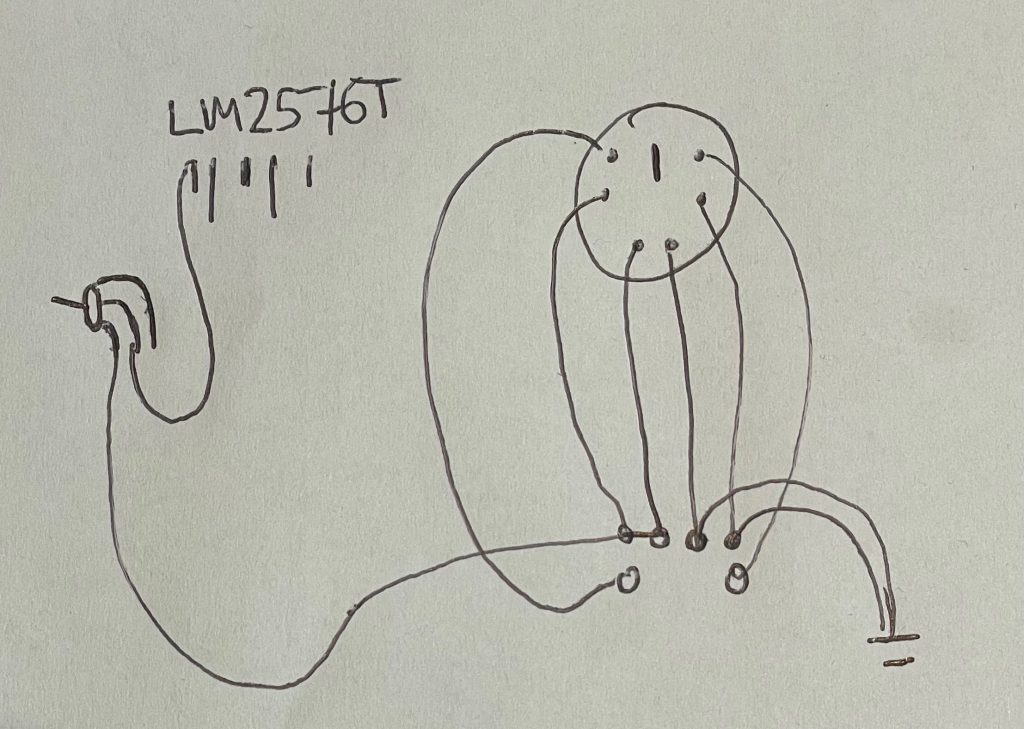
The input is first passed through the input switch, meaning the switch actually removes all power to the unit by switching off the regulator. The LM2576T voltage regulator generates 5V for the logic; there is another regulator inside the unit for generating the -9V from the +5V rail.
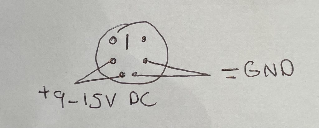
Above is a simple drawing for determining how to power the Cisco 751. There are 2 pins for GND and 2 pins for +VCC, which can be anything between 9 and 15 VDC.
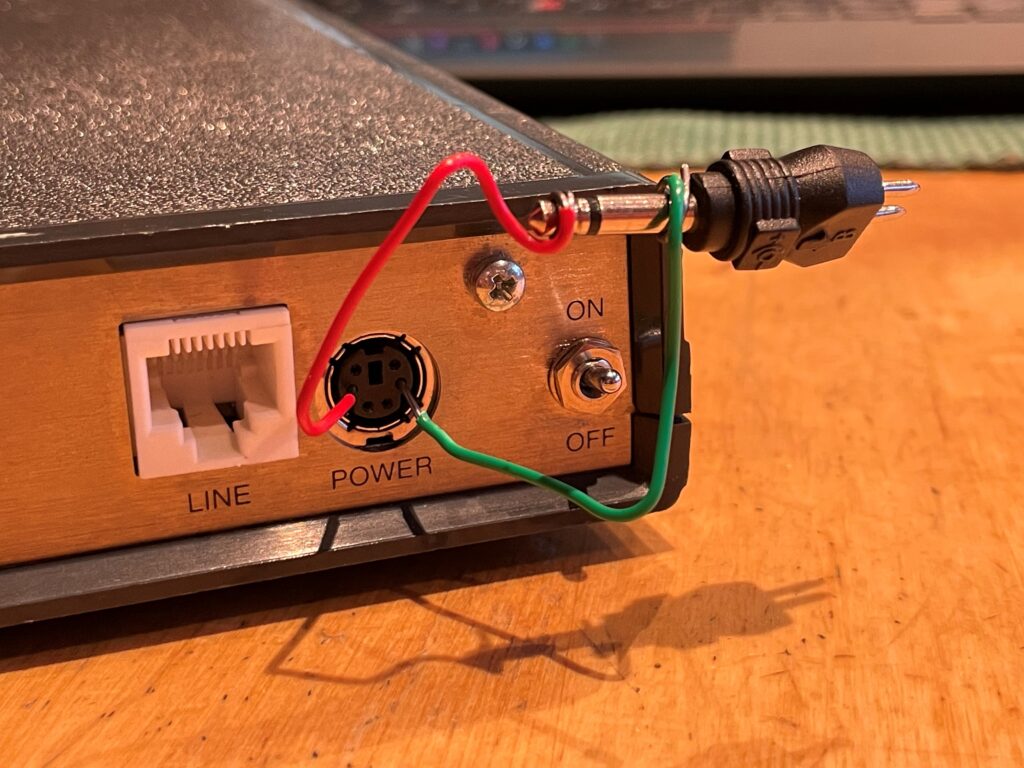
Being home for the holidays, finding the correct test equipment proved difficult and I had to make do with I found- in this instance a 3.5mm DC jack and a couple of paper clips which were carefully inserted into the DIN-plug in the back of the box. On the first power up, afraid to let the magic smoke out, I started at 9V to minimize any possible damage to the unit.
But what do you know…. it works!
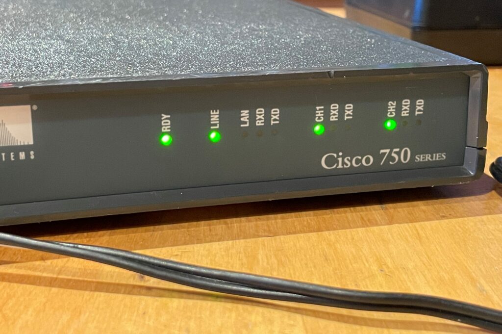
The unit flashed up with green leds, starting the usual ISDN connection procedure just like it hadnt been 20 years since it was last used. Eager to find what secrets this time capsule has been hiding all these years, I grabbed my go-to Cisco serial cable from my bag to connect it to the serial port.
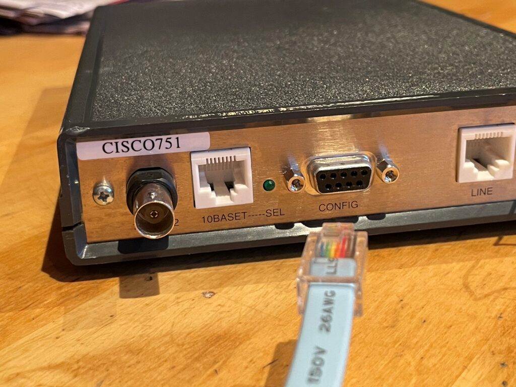
Yeah, that did not work. This thing precedes the blue-Cisco-serial-port era, sporting a standard DB9-plug. This would normally not be an issue as I have serial cables for days, but remember the part about being home for the holidays without my stuff? Yep.
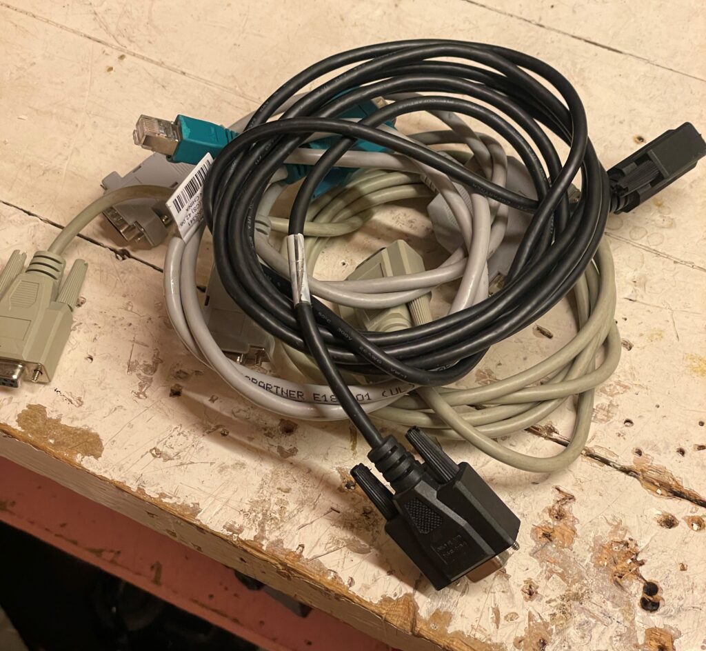
Even though I was able to grab a hold of more serial cables than most people have lying around at home, I could not find a single one up for the task. Some were null-modem, some were a completely different proprietary pinout.
How then?
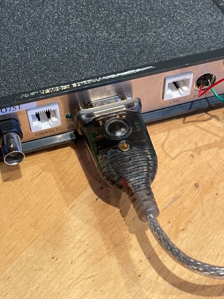
Bingo! Simply a case of unscrewing the standoffs and mashing the USB-adaptor right into the plug.
Expectedely, I was met with a password protected prompt when booting the unit. Unfortunately all my password-recovery tricks were unable to get me into this thing as it preceedes most of any Cisco hardware. Adding the fact that there is no documentation for this thing online, I decided to leave it at that at come back to it at a later point.